


E-4 E-4
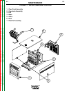
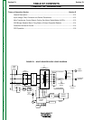
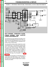
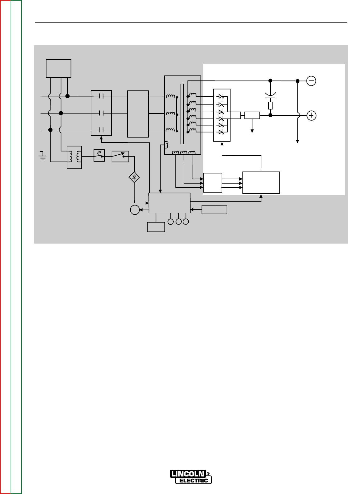
FIGURE E.4 – SCR BRIDGE, RESISTOR BANK, FIRING BOARD, & OUTPUT CAPACITOR/RESISTOR
TROUBLESHOOTING & REPAIR
MULTI-SOURCE
Return to Section TOC Return to Section TOC Return to Section TOC Return to Section TOC
Return to Master TOC Return to Master TOC Return to Master TOC Return to Master TOC
SCR BRIDGE, RESISTOR BANK,
FIRING BOARD, AND OUTPUT
CAPACITOR/RESISTOR
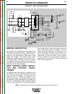
The neutrals of the main transformer secondary wind-
ings are connected together and the six starts are con-
nected to the six SCR assemblies to form a six phase
output. This six phase AC output is rectified and con-
trolled through the SCR bridge.
The firing board receives power through the current
limiting resistor bank. The firing board is a three phase
circuit. Each phase provides two firing pulses; one for
each of the two Silicon Controlled Rectifiers (SCRs)
controlled by that particular phase. The firing circuit
supplies the proper amount of energy to the gates of
the power SCRs. When the gate signal is applied, at
the correct time, the SCR will turn on and conduct cur-
rent. The amount of "ON" timer versus "OFF" time
determines the output of the machine. See SCR
Operation.
A capacitor filter and resistor are connected across the
output leads on the Multi-Source. This is required to
reduce and limit the output voltage peaks. The capac-
itor ripple current (greatest with light resistive loads) is
limited by the resistor.
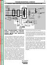
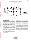
LED LED LED
DIGITAL
METER
G
Y
W
CONTROL
BOARD
THERMOSTAT
CONTROL
SIGNAL
RESISTOR
BANK
FIRING
BOARD
GATE SIGNALS
TO CONTROL
BOARD
SHUNT
SCR OUTPUT RECTIFIER
FILTER
CAPACITOR
LIMITING
RESISTOR
WORK
TERMINAL
ELECTRODE
TERMINAL
T1
MAIN
TRANSFORMER
INPUT
CONTACTOR
CONTROL
TRANSFORMER
THERMOSTAT
SWITCH
CONTROL
BOX
RECTIFIER
FAN
R
E
C
O
N
N
E
C
T
SURGE
NOISE
FILTER
T2
FAN VOLTAGE
120 VAC
CONTACTOR
32 VAC
32 VAC
32 VAC
TO CONTROL
BOARD