


E-3 E-3
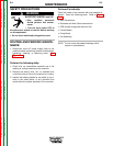
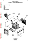
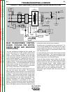
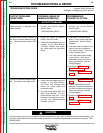
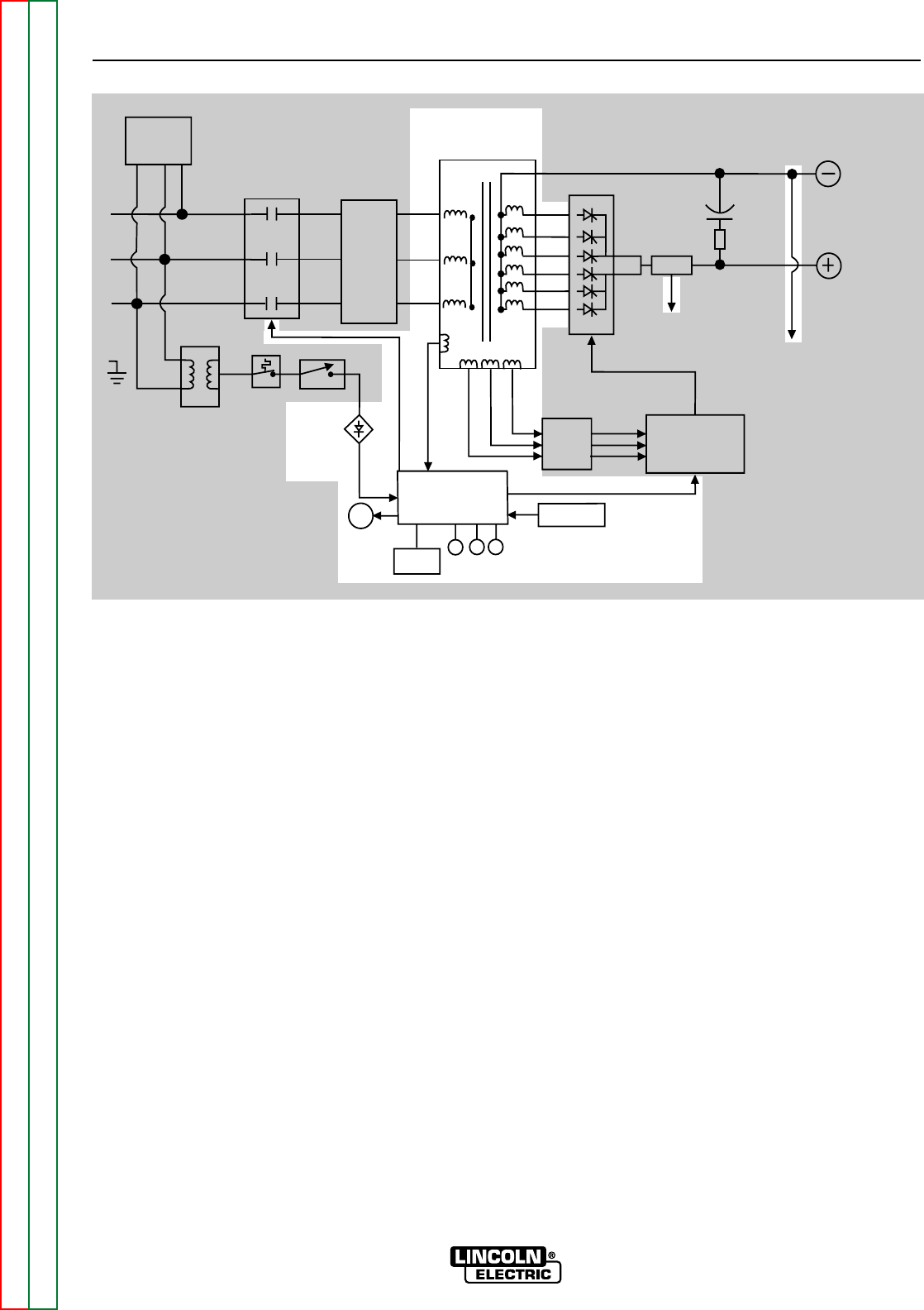
FIGURE E.3 – MAIN TRANSFORMER, CONTROL BOARD, COOLING FAN MOTOR, & LEDs
TROUBLESHOOTING & REPAIR
MULTI-SOURCE
Return to Section TOC Return to Section TOC Return to Section TOC Return to Section TOC
Return to Master TOC Return to Master TOC Return to Master TOC Return to Master TOC
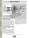
MAIN TRANSFORMER, CONTROL
BOARD, COOLING FAN MOTOR,
DIGITAL METER AND INDICATOR
LIGHTS (LEDs)
The main transformer changes the high voltage, low
current input power to a lower voltage, higher current
output. The finishes or "neutrals" of the main sec-
ondary coils are connected together and the six starts
of the secondary windings are connected to the SCR
output rectifier assembly. In addition the main trans-
former has an isolated 120VAC (nominal) winding the
supplies 120VAC, via the control board, to operate the
cooling fan motor. The three isolated 32VAC (nominal)
phase angle windings are also housed in the main
transformer assembly. These windings provide power
and "timing" information to the firing board.
The control board receives a widely-varying DC volt-
age from the control box rectifier. The switching
power supplies, that are housed on the control board,
supply DC current to the control circuits and the input
contactor. The control board receives current feed-
back information from the output shunt, voltage feed-
back information from the output terminals and tem-
perature information from several thermostats. This
feedback information is processed by the control
board. The control board then sends the appropriate
gate firing signals to the firing board, output informa-
tion to the digital meter and command signals to the
cooling fan motor and the input contactor.
The cooling fan is controlled by the control board. The
F.A.N. (fan as needed) will be activated with an output
current greater than 20 amps. It can also be activated
(via the control board) by a thermostat located on the
main transformer iron.
A current sensing circuit on the control board controls
the digital meter display. This meter provides the user
with an indication of the percentage of available power
that is being drawn from the Multi-Source.
There are three indicator lights located on the front
panel of the Multi-Source. The green safe output light
indicates when the machine's output voltage is within
the safe operating range. Other indicator lights
include the amber thermal light that indicates the ther-
mostat, located on the negative output lead, has
opened due to an over temperature condition. The
white power light indicates when the control board is
energized.
LED LED LED
DIGITAL
METER
G
Y
W
CONTROL
BOARD
THERMOSTAT
CONTROL
SIGNAL
RESISTOR
BANK
FIRING
BOARD
GATE SIGNALS
TO CONTROL
BOARD
SHUNT
SCR OUTPUT RECTIFIER
FILTER
CAPACITOR
LIMITING
RESISTOR
WORK
TERMINAL
ELECTRODE
TERMINAL
T1
MAIN
TRANSFORMER
INPUT
CONTACTOR
CONTROL
TRANSFORMER
THERMOSTAT
SWITCH
CONTROL
BOX
RECTIFIER
FAN
R
E
C
O
N
N
E
C
T
SURGE
NOISE
FILTER
T2
FAN VOLTAGE
120 VAC
CONTACTOR
32 VAC
32 VAC
32 VAC
TO CONTROL
BOARD