


F-14 F-14
TROUBLESHOOTING & REPAIR
MULTI-SOURCE
Return to Section TOC Return to Section TOC Return to Section TOC Return to Section TOC
Return to Master TOC Return to Master TOC Return to Master TOC Return to Master TOC
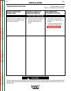
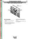
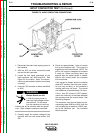
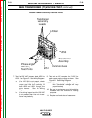
INPUT CONTACTOR TEST (Continued)
CONTACTOR
COIL
240
241
1. Disconnect the main input supply power to
the machine.
2. With the 3/8” nut driver, remove the case
top and the left case side.
3. Locate the two leads connected to the
input contactor coil, #240 and #241. See
Figure F.3 for location. Note: The discon-
nects may be located inside the loom (lead
covering).
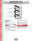
4. Connect a DC ammeter to either lead #240
or #241.
Electric Shock can kill.
• With the input power on,
there are high voltages inside
the machine. Do not reach
into the machine or touch any
internal part of the machine while the power
is on. High voltage is present at terminals.
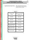
5. Carefully apply the correct voltage to the
machine and turn the power switch (S1)
ON.
6. Check for approximately 1 amp of current
flow at the contactor coil. This current is
supplied by the Control Board. NOTE: The
pull-in coil current is designed to be about
5 amps for 100ms occurring about one
second after the power switch is closed.
Without this current pulse, the contactor
will not activate.
If the current is present and the contactor
does NOT activate, then the input contac-
tor coil may be faulty, or the contactor’s
moving parts may be stuck. The normal
coil resistance is approximately 4.0 ohms.
If the 1 amp DC current is NOT present,
check the continuity of the leads between
the contactor and the control board. See
the Wiring Diagram.
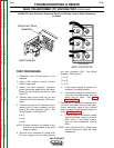
The contactor may also be tested by dis-
connecting leads #240 and #241 from the
coil and applying an external 120VAC sup-
ply to the contactor coil. The contactor
should activate.
FIGURE F.3. INPUT CONTACTOR CONNECTIONS
WARNING