


F-32 F-32
CONTROL BOARD TEST (Continued)
TROUBLESHOOTING & REPAIR
MULTI-SOURCE
Return to Section TOC Return to Section TOC Return to Section TOC Return to Section TOC
Return to Master TOC Return to Master TOC Return to Master TOC Return to Master TOC
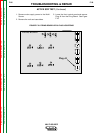
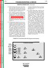
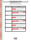
J1
J2
J3
J5
J6
J8
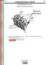
Firing Board
Control Board
J4
J7
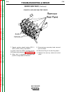
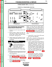
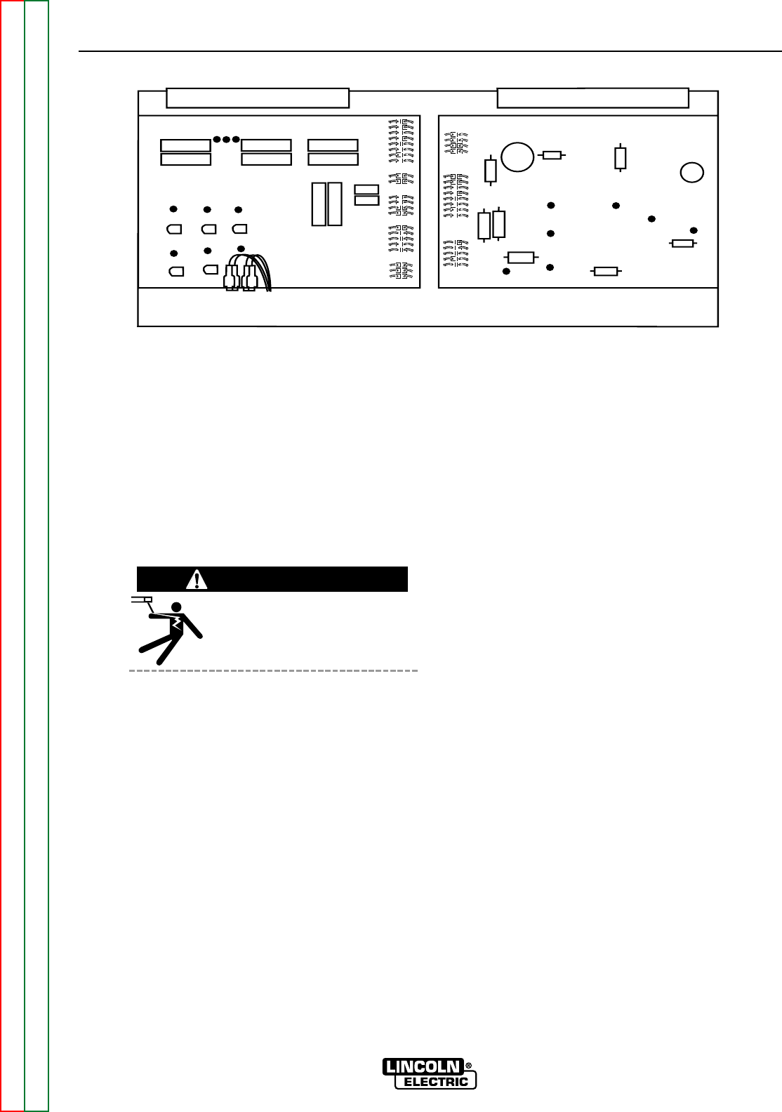
TEST PROCEDURE FOR NORMAL CON-
TROL BOARD OPERATION
1. Remove main supply power to the Multi-
Source.
2. Remove screws, loosen and lower the
front panel to access and inspect the con-
trol board located in the right side of the
control box. See Figure F.14.
3. Apply the correct three-phase input power
to the Multi-Source. Turn on the machine.
WHEN THE MULTI-SOURCE IS
TURNED ON, THE OUTPUT
TERMINALS ARE ELECTRICAL-
LY HOT.
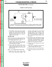
4. The white power light, located on the front
control panel, indicates the control board
is receiving the DC voltage that is supplied
from the rectified secondary voltage of the
control transformer. This voltage can
range from 38VDC with 345VAC applied to
the machines input, to 58VDC with
600VAC applied to the Multi-Source. This
voltage can be measured at Plug J2-pin4
(+) lead #274, to plug J2-pin2 (-) lead
#273. See Figure F.15. Normal voltage
on the white light is 3.5VDC. If 5.0VDC is
present the light may be open. This can
be measured at plug J1-pin 7(+) lead #230
to plug J1-pin 8(-) lead #341.
5. LED 1 is an indication of the machine’s
output voltage. At normal output voltages
LED1 should be brightly lit. Normal open
circuit voltage (OCV) at the welding output
terminals is approximately 80VDC. This
voltage can be checked at Plug J1-pin 1(+)
lead #201 to Plug J1-pin 9(-) lead #222A.
If the voltage is correct but LED1 is not lit,
the control may be faulty. See Figure
F.15.
6. LED 2 indicates the level of the control sig-
nal that is passed to the firing board. The
brightness of LED 2 is inversely propor-
tional to the output of the machine. As the
control signal decreases (LED 2 gets dim-
mer) the machine’s output increases. The
control signal can be measured at Plug J1-
pin 4(+) lead #231 to Plug J1-pin1(-) lead
#201. Normal range is about 12VDC at
open circuit to about 3VDC when high or
maximum output is required. See Figure
F.15.
7. LED 3 indicates that the machine’s output
is greater than 10 amps and the control
board is developing a signal for the cool-
ing fan to operate. This signal activates a
fan motor driver circuit that is incorporated
within the control board. See step 10 (LED
6).
8. LED 4 is an indication that either a ther-
mostat, output current or output over-cur-
rent is calling for the fan motor to operate.
See Figure F.15.
9. LED 5 lights when the current feedback
signal from the output shunt is too high. If
LED 5 is lit for 5-8 seconds, the enable
signal from the control board to the firing
board is sent high (over 12VDC) (LED2). If
the output current overload is of a short
time duration LED 5 may only be lit briefly.
In either case the machine’s output will be
zero and the output will remain off for
about 75 seconds. See Figure F.15.
FIGURE F.14. CONTROL BOARD LOCATION
WARNING