


F-36 F-36
FIRING BOARD TEST (Continued)
TROUBLESHOOTING & REPAIR
MULTI-SOURCE
Return to Section TOC Return to Section TOC Return to Section TOC Return to Section TOC
Return to Master TOC Return to Master TOC Return to Master TOC Return to Master TOC
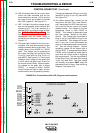
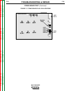
J1
J2
J3
J5
J6
J8
Firing Board
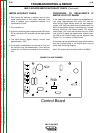
Control Board
J4
J7
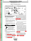
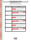
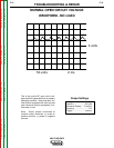
TEST PROCEDURE FOR NORMAL
FIRING BOARD OPERATION
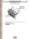
1. Disconnect main AC input power to the
machine.
2. Remove screws, loosen and lower the
front panel to access the firing board on
the left side of control box while facing
the machine. See Figure F.16.
3. Visually inspect the Firing Board for loose
or faulty connections and obvious physi-
cal damage.
Electric Shock can kill.
• With the input power on,
there are high voltages inside
the machine. Use caution
when reaching into the
machine or touching any internal part of the
machine while the power is on. High voltage
is present.
4. Reconnect the input power and turn the
MULTI-SOURCE on.
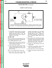
5. Locate LEDs 7, 8, and 9 on the Firing
Board. See Figure F.17. Each LED should
be ON and equally bright. Use Table F.2
to check LED operation.
6. Make certain that plug J7 (jumper plug) is
in place. See Figure F17. and the wiring
diagram.
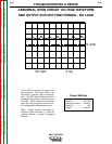
NOTE: To verify that the control board is
sending the correct output enable signal to
the firing board, check from plug J8, pin 7(+)
(lead #340) to plug J5, pin 12 (-) (lead #215).
See Figure F.17. See the wiring diagram.
Normal voltage is approximately less than 1.0
VDC. If not correct the control board may be
faulty.
7. Locate LEDs 1 thru 6. Each LED should
glow with equal brightness.
NOTE: LEDs 1 through 6 indicate that the
gate firing signals are being generated to
send to each of the output SCRs.
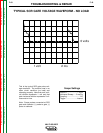
8. If LED 2, located on the control board, is
bright along with LEDs 7,8 and 9 on the
Firing Board and LEDs 1 through 6 are
unequal in brightness, check to make
sure lead #231 is not loose or broken. See
the wiring diagram. Normal voltage range
at plug J5, pin 13 (+) (lead #231) to plug
J5, pin 12 (-) (lead #215) is 3 to 13 VDC.
At an open circuit condition the normal
voltage is approximately 10 VDC. See
Figure F.17.
9. If one or two of the LEDs 1 through 6
are dimmer or brighter than the others,
this could indicate an open or shorted
gate on an output SCR. Perform the
Static and Active SCR Tests.
WARNING
FIGURE F.16. FIRING BOARD LOCATION