


Return to Section TOC Return to Section TOC Return to Section TOC Return to Section TOC
Return to Master TOC Return to Master TOC Return to Master TOC Return to Master TOC
TROUBLESHOOTING & REPAIR
F-4 F-4
MULTI-SOURCE
TROUBLESHOOTING GUIDE Observe Safety Guidelines
detailed in the beginning of this manual.
CAUTION
If for any reason you do not understand the test procedures or are unable to perform the test/repairs safely, con-
tact the Lincoln Electric Service Department for electrical troubleshooting assistance before you proceed. Call 1-
800-833-9353.
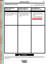
OUTPUT PROBLEMS
(SYMPTOMS)
POSSIBLE AREAS OF
MISADJUSTMENT(S)
RECOMMENDED
COURSE OF ACTION
OUTPUT PROBLEMS
Major physical or electrical dam-
age is evident.
1. Contact the Lincoln Electric
Service Dept.
1-800-833-9353 (WELD)
1. Contact the Lincoln Electric
Service Dept.
1-800-833-9353 (WELD)
Machine Multi-Source is dead and
the input contactor does not oper-
ate. The white power light is NOT
lit.
The input contactor does not oper-
ate. The white power light is ON.
1. Check for blown or missing
fuses in the input lines.
2. Check the three phase input line
voltage at the Multi-Source.
The input voltage must match
the rating plate and reconnect
panel.
1. Check the three phase input line
voltage at the Multi-Source.
The input line voltage must
match the rating plate and
reconnect panel.
2. Turn the power switch OFF and
wait a few seconds. Turn the
power switch back ON. If the
problem is not resolved, contin-
ue with the “Recommended
Courses of Action”.
1. The ON/OFF switch may be
faulty. Check switch and asso-
ciated leads. See the Wiring
Diagram.
2. The thermostat, located on the
rear of the main transformer
iron, may be faulty. This is nor-
mally a closed device.
3. The control box diode bridge
may be faulty. Also check
associated wiring for loose or
faulty connections. See the
Wiring Diagram.
4. Perform the T2 Control
Transformer Test.
5. Perform the Control Board
Test.
1. Perform the Input Contactor
Test.
2. Check leads #240 and #241
between the control board and
the input contactor for loose or
faulty connections. See the
Wiring Diagram.
3. Perform the Control Board
Test.
4. Perform the SCR Rectifier
Bridge Test.