


F-55 F-55
TROUBLESHOOTING & REPAIR
MULTI-SOURCE
Return to Section TOC Return to Section TOC Return to Section TOC Return to Section TOC
Return to Master TOC Return to Master TOC Return to Master TOC Return to Master TOC
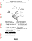
SCR BRIDGE / HEAT SINK ASSEMBLY REPLACEMENT PROCEDURE
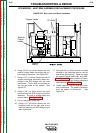
6. Using a 9/16” nut driver, remove the two
positive output leads connecting the out-
put bridge to the shunt. See Figure F.27.
7. Using a 1/2” nut driver disconnect the six
copper transformer secondary leads con-
nected to the SCR bridge from the main
transformer. Three leads are located on
the top and three on the bottom. See
Figure F.27.
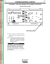
8. Using a 3/8” nut driver remove the right
bolt mounting the SCR bridge to the front
assembly. The bolt is located below the
control board. See Figure F.28.
9. Cut any necessary cable ties.
10. Using a 1/2” nut driver, remove the two
mounting bolts on the right side of the
machine mounting the SCR bridge to the
main transformer.
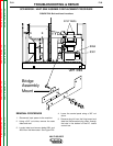
11. Using a 9/16” nut driver, remove two bolts
covered in red insulating paint on the left
side of the machine only. These two bolts
are located above leads #301 and #264.
See Figure F.26. Note position of insula-
tion, nut, bushing, and washer placement
upon removal. See Figure F.26.
12. Locate, label and remove lead #251 from
main transformer. The solder connection
must be broken to disconnect. See
Figure F.27.
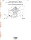
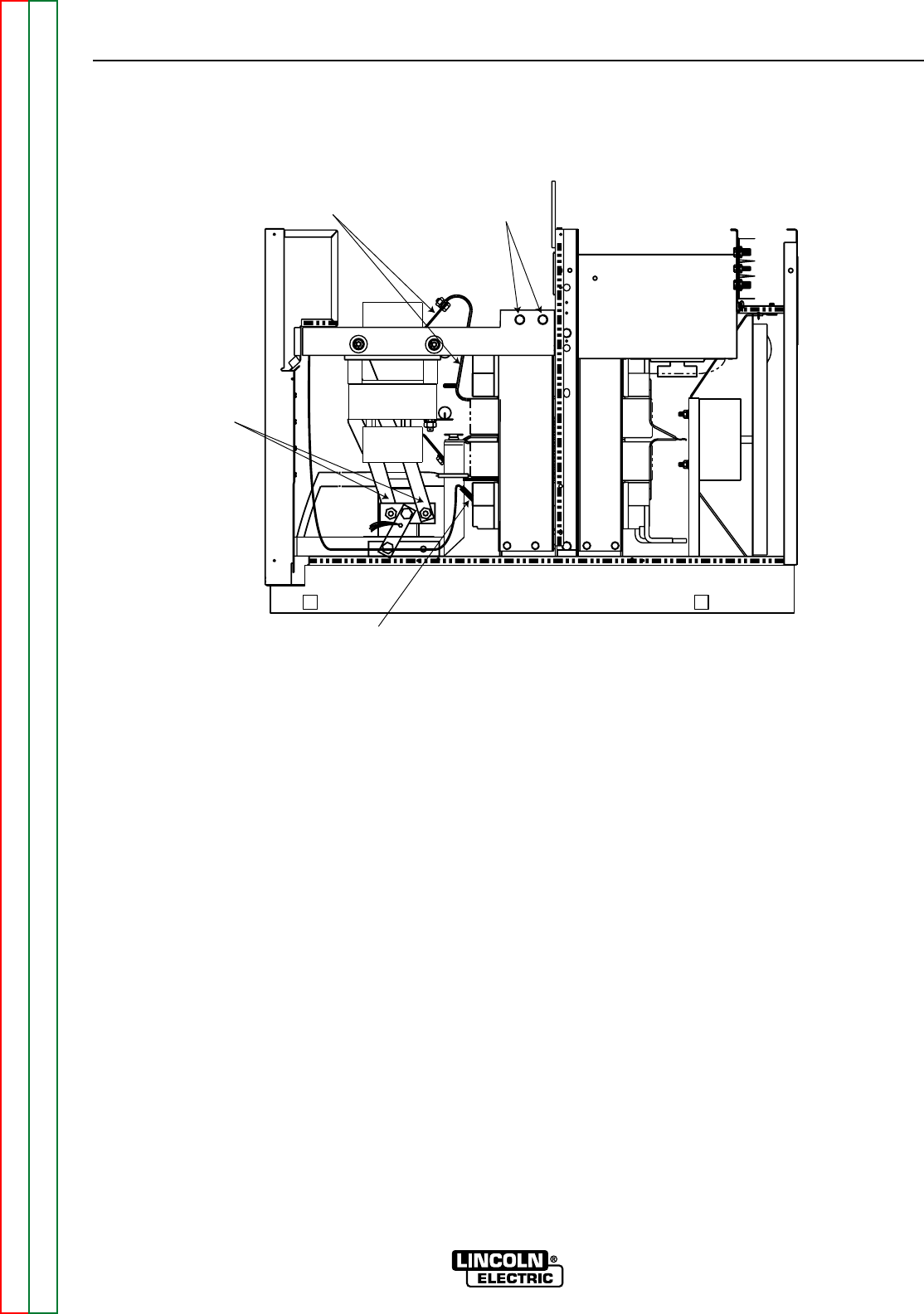
FIGURE F.27. Bolt, Lead, and Shunt Locations
RIGHT SIDE
1/2" Bolts
Copper Leads
#251
Positive
Output
Leads