


OPERATION
B-4 B-4
MULTI-SOURCE
Return to Section TOC Return to Section TOC Return to Section TOC Return to Section TOC
Return to Master TOC Return to Master TOC Return to Master TOC Return to Master TOC
RECOMMENDED EQUIPMENT/CONNECTIONS
The Multi-weld 350 (K1735-1) is the recommended means by which to control the MULTI-SOURCE power supply.
Connections between the MULTI-SOURCE and the Multi-weld may be easily made using Twist-Mate male and
female connectors and the K1736-1 Distribution box.
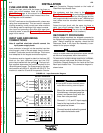
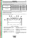
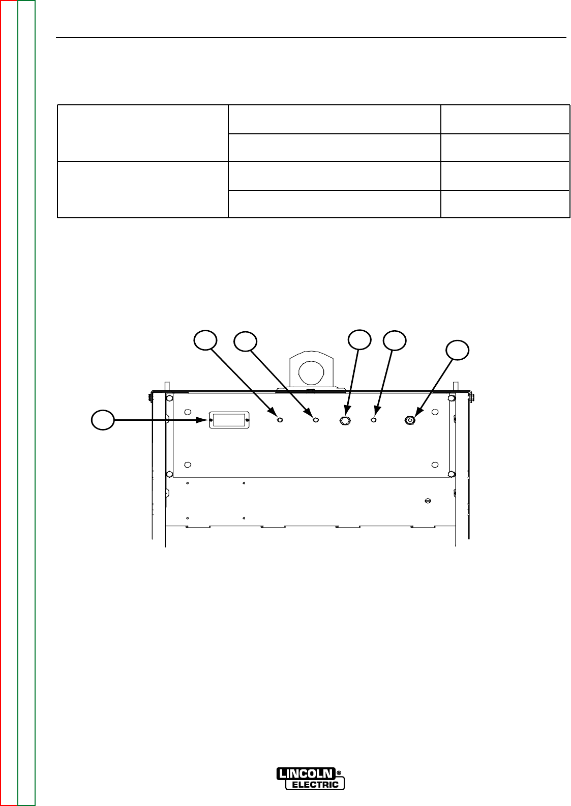
1. ON/OFF TOGGLE SWITCH: This toggle
switch turns the machine ON or OFF.
2. CIRCUIT BREAKER:
This 10 amp
breaker protects the 120 VAC fan circuit.
3. AMBER LED:
This
LED indicates that
the temperature of the machine is too
high.
4. WHITE LED:
This
LED indicates that the
control board is energized.
5. GREEN LED:
This LED indicates that the
machines output voltage is within the safe
operating range.
6. DIGITAL METER: Provides the user with
an indication of the percentage of avail-
able power.
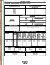
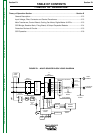
For 1/0 Cable
K852-70
K1759-70
K852-90
K1759-90
Twist-Mate Male Connector
Twist-Mate Female Connector
Twist-Mate Male Connector
Twist-Mate Female Connector
For 3/0 Cable
The Multi-weld 350 has multi-process capability and may be used in manual and semi-automatic processes. When
a wire feeder is required an LN-25 (K449) is recommended. The number of Multi-Weld 350s, the procedures used
and the combined duty cycle of the arcs are only limited by the 40,000 watt (36,000 watts on 50 Hz) rating of the
Multi-Source supply. The machine is IP-23S rated and is designed for outdoor applications.
% Output
Output
Thermal
Fan
Power
On
OFF
6
5
3
2
4
1
CONTROLS AND SETTINGS
All operator controls and adjustments are located on the Case Front Assembly of the MULTI-SOURCE. See
Figure B.1. below for the location of each control.
FIGURE B.1. - CONTROL PANEL