


F-33 F-33
CONTROL BOARD TEST (Continued)
TROUBLESHOOTING & REPAIR
MULTI-SOURCE
Return to Section TOC Return to Section TOC Return to Section TOC Return to Section TOC
Return to Master TOC Return to Master TOC Return to Master TOC Return to Master TOC
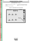
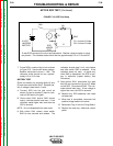
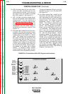
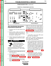
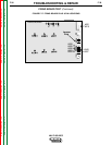
FIGURE F.15. Control Board with LED, Plug and Lead Locations
10. LED 6 indicates that the fan motor driver
circuit has been activated and the fan
motor should be running. LED 6 and the
fan motor will be on for about 5 minutes
after LED 4 goes off. See Figure F.15.
11. LED 7 will light if a positive voltage is pre-
sent on the negative output terminal (AC
instead of DC). This is an indiction of a
shorted SCR in the output bridge rectifier.
See SCR Rectifier Bridge Test. The
input contactor will open and will remain
deenergized until the power switch is
turned off for a minimum of 1 second. See
Figure F.15.
12. The green light, located on the front con-
trol panel, is lit when the machine’s output
voltage is present and at a safe level. The
voltage range is from 40VDC to 113VDC
peak. This voltage can be measured at
the output terminals and verified at Plug
J1-pin 6(+) lead #215 to Plug J2-pin 1(-)
lead #222D. See Figure F.15. If the output
voltage is within range but the green light
is not lit either the green light is faulty or
the control board is faulty. Normal operat-
ing voltage for the green light is about
3.5VDC. A voltage of about 5.0VDC
would indicate the light is open and the
control board circuit is operating correctly.
This can be measured at Plug J1-pin 16(+)
lead #232 to Plug J1-pin 15(-) lead #233.
See Figure F.15.
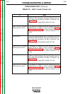
13. The yellow (amber) light, located on the
front panel, will light if the “open thermo-
stat” (secondary and SCR heat sink) sig-
nal is sent to the fan control and output
disable circuits. The voltage on the two
thermostat circuit is from 24VDC to
38VDC. This voltage is dependent upon
the input voltage applied to the Multi-
Source. This voltage can be verified at
Plug J1-pin 3(+) lead #263 to Plug J1-pin
11(-) lead #264. This voltage will be pre-
sent if only one of the thermostats are
open or an associated lead is disconnect-
ed. See the Wiring Diagram. Normal
operating voltage for the amber light is
about 2.2VDC. A voltage reading of about
5.0VDC would indicate the amber light is
open and the control board is supplying
the correct signal. This can be verified at
Plug at Plug J1-pin 13(+) lead #234 to plug
J1-pin 12(-) lead #235. This light voltage
will normally be present ONLY when the
thermostat circuit is open. See the Wiring
Diagram. See Figure F.15.
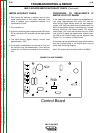
CONTROL BOARD
J1
J2
J3
#222A
#201
#263
#231
#230
#215
#341
#232
#233
#234
#235
#264
#222D
#273
#274