


F-50 F-50
CONTROL BOARD REPLACEMENT PROCEDURE (Continued)
TROUBLESHOOTING & REPAIR
MULTI-SOURCE
Return to Section TOC Return to Section TOC Return to Section TOC Return to Section TOC
Return to Master TOC Return to Master TOC Return to Master TOC Return to Master TOC
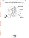
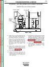
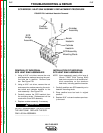
J1
J2
J3
J5
J6
J8
Firing Board
Control Board
J4
J7
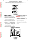
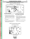
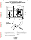
REMOVAL PROCEDURE
1. Disconnect input power to the machine.
2. Using a 3/8” nut driver, remove screws and
lower the front control panel to access the
control board on the right side of control
box while facing the machine. See Figure
F.22.
3. Disconnect plugs J2, J1, and J3 from the
control board.
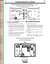
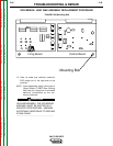
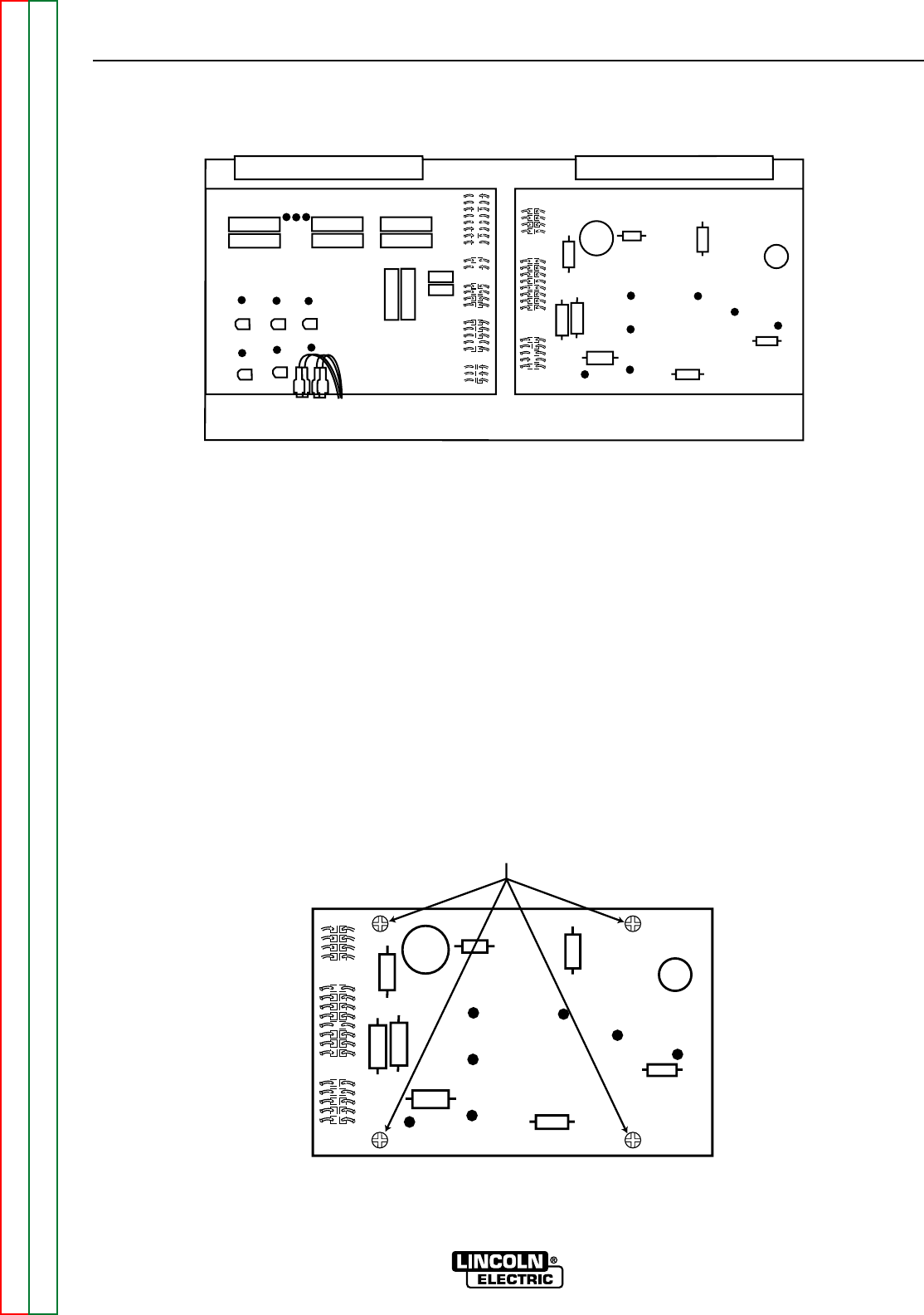
4. Remove the four phillips head screws and
associated washers from the corners of
the control board. See Figure F.23.
5. Carefully remove the control board.
REPLACEMENT PROCEDURE
1. Replace the control board.
2. Mount the control board to the machine in
its proper position using the four phillips
head screws and associated washers pre-
viously removed.
3. Reconnect plugs J3, J1, and J2 to the con-
trol board.
4. Replace the four screws previously
removed from the front control panel.
FIGURE F.22. FRONT PANEL W/OUT COVER
J1
J2
J3
Control Board
MOUNTING SCREWS
FIGURE F.23. MOUNTING SCREW LOCATIONS