


F-57 F-57
TROUBLESHOOTING & REPAIR
MULTI-SOURCE
Return to Section TOC Return to Section TOC Return to Section TOC Return to Section TOC
Return to Master TOC Return to Master TOC Return to Master TOC Return to Master TOC
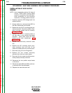
REMOVAL OF INDIVIDUAL
SCR HEAT SINK ASSEMBLIES
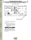
1. Using a 9/16” nut driver, remove the nuts
and respective washers securing the posi-
tive buss bar in position. Remove buss
bar. See Figure F.29.
2. Using a 9/16” nut driver, remove the nut
and respective washers securing the snub-
ber board and cathode heatsink to the
main assembly. See Figure F.29.
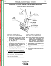
3. Carefully remove the SCR heatsink from
the mounting studs. Replacement will be
made with a new SCR assembly.
4. Replace snubber assembly if necessary.
DO NOT DISASSEMBLE THE SCR FROM
THE HEAT SINK. REPLACE THE SCR
ONLY AS AN ASSEMBLY.
---------------------------------------------------
INSTALLATION OF INDIVIDUAL
SCR HEAT SINK ASSEMBLIES
NOTE: Upon reassembly, apply a thin layer of
Lincoln T12837 (Dow Corning #340)
heat sink compound to all bolted elec-
trical connections on the aluminum
heat sinks, including positive buss bar.
1. Carefully position new SCR assembly on to
heatsink mounting studs.
2. Place positive buss bar back in original
position.
3. Replace 9/16” nuts and washers previous-
ly removed.
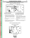
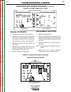
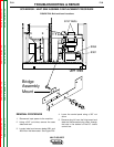
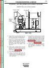
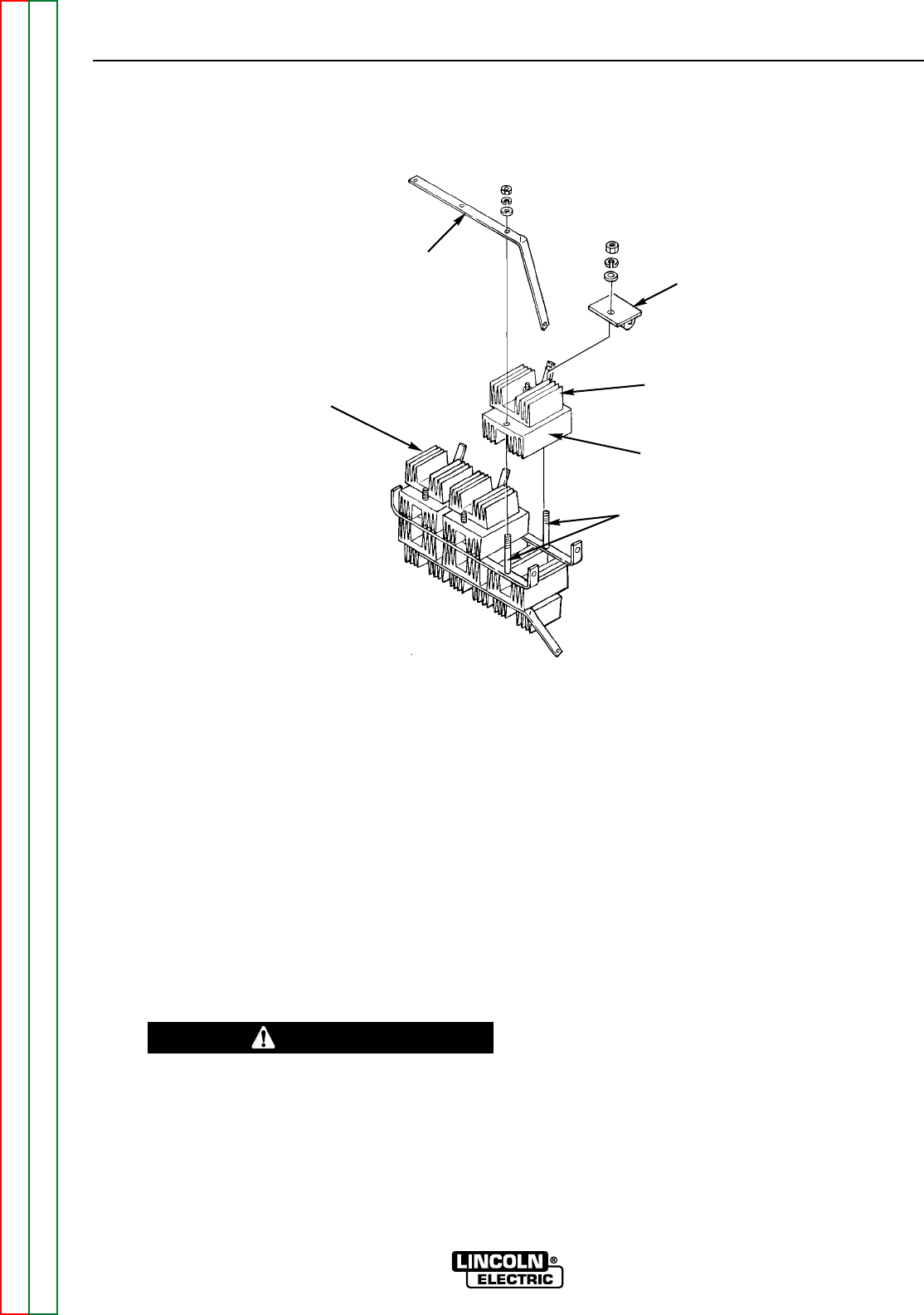
SCR BRIDGE / HEAT SINK ASSEMBLY REPLACEMENT PROCEDURE
FIGURE F.29. Individual Heatsink Removal
SCR Assembly
Mounting Studs
Anode
Heatsink
Cathode
Heatsink
Snubber
Assembly
Positive
Buss Bar
SCR
Bridge
Assembly
CAUTION