


INSTALLATION
A-4 A-4
POWER FEED® 25M
Return to Section TOC Return to Section TOC Return to Section TOC Return to Section TOC
Return to Master TOC Return to Master TOC Return to Master TOC Return to Master TOC
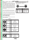
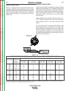
CONTROL CABLE CONNECTION:
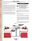
Digital Control Cable: Figure A.3
P
o
wer
S
ource
AA
BB
CC
DD
EE
W
i
re
Feeder
AA
BB
CC
DD
EE
Power Source
Pin Function
A Digital I/O
B Digital I/O
C "67" voltage sense
D 40 VDC
E Common
Wire Feeder
Pin Function
A Digital I/O
B Digital I/O
C "67" voltage sense
D 40 VDC
E Common
AA
BB
CC
DD
EE
AA
BB
CC
DD
EE
AA
BB
CC
DD
FF
EE
AA
BB
GG
CC
DD
FF
EE
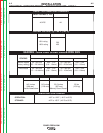
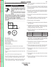
Function
5 pin trigger con-
nector for push-
only guns.
6 pin connector for
remote control or
foot/hand amptrol.
7 pin connector for
push-pull guns
Function
5 pin ArcLink con-
nector.
PIN
A
B
C
D
E
A
B
C
D
E
F
A
B
C
D
E
F
G
PIN
A
B
C
D
E
Wiring
Trigger
Not used
Trigger, Common
Dual Procedure Selection
Dual, Common
77 Remote potentiometer, 5K
75 Remote potentiometer, common
76 Remote potentiometer, wiper
Switch, On/Off
Switch, common
Not used
Motor -
Motor +
77 Remote potentiometer, 5K
76 Remote potentiometer, wiper
Switch, On/Off
Switch, common
75 Remote potentiometer, common
Wiring
ArcLink
ArcLink
67 Electrode Voltage Sense
40VDC
40VDC, Common
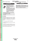
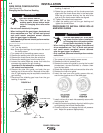
CABLE CONNECTIONS
There are three circular connectors on the front of the
POWER FEED® 25M.
There is one circular connector on the rear of the POWER FEED® 25M.
DIGITAL CONTROL CABLE, K1543-XX
(See Figure A.3)
ArcLink/LincNet control cables are special high quality
cables for digital communication. The cables are cop-
per 5 conductor cable in a SO-type rubber jacket.
There is one 20 gauge twisted pair for network com-
munications. This pair has an impedance of approxi-
mately 120 ohms and a propagation delay per foot of
less than 2.1 nanoseconds. There are two 12 gauge
conductors that are used to supply 40VDC to the net-
work. The fifth wire is 18 gauge and is used as an elec-
trode sense lead.
Use of non-standard cables may lead to system shut-
downs, poor arc starting and wire feeding problems.
The control cables connect the power source to the
wire feeder, and the wire feeder to other wire feeders.
Control cables may be connected end to end to extend
their length. Use a maximum of 200 ft. (61.0m) of con-
trol cable between components.
FIGURE A.1
FIGURE A.2