


OPERATION
B-21 B-21
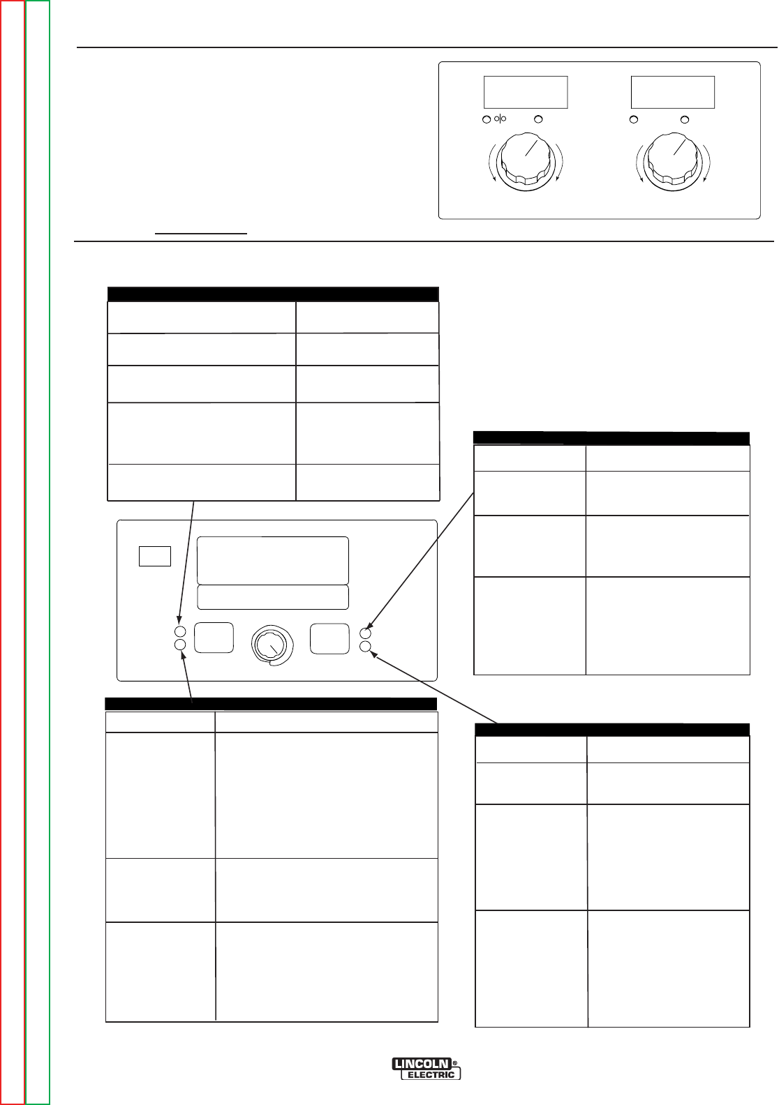
POWER FEED® 25M
Return to Section TOC Return to Section TOC Return to Section TOC Return to Section TOC
Return to Master TOC Return to Master TOC Return to Master TOC Return to Master TOC
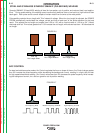
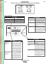
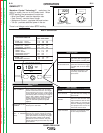
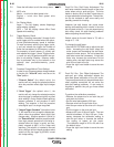
GMAW-STT™
Waveform Control Technology™ maximizes the
ability to modify the arc for the perfect weld. When
STT™ welding, the parameters to control are:
• Wire Feed Speed - sets the deposition rate.
• Peak Current - controls the arc length.
• Background Current - regulates the bead contour.
• Tail-out - provides additional power in the arc.
There is no Voltage control
when STT™ welding.
220
----
WFS AMPS
V
OLTS TRIM
Less
Deposition
More
Deposition
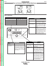
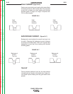
EFFECT / RANGE
PEAK CURRENT
BACKGROUND
CURRENT
TAIL OUT
(
STT ll MODES
ONLY)
DESCRIPTION
Peak Current acts similar to an
arc
pinch
control. Peak Current
sets the arc length
and
promotes
-
good fusion.
Higher
peak
current levels will cause
the arc to broaden
momentarily
while increasing arc length. If
set too high, globular transfer
may occur.
Setting it too low
may cause instability
and
wire
stubbing.
Best
practice is to
adjust for minimum spatter and
puddle
agitation.
Background Current controls
the
overall
heat input in the
weld.
Tail out provides additional
power
without the molten
droplet becoming
too
large.
Increase as necessary to add
heat input without increasing
arc length.
Often this results in
faster travel speeds.
Note that
as tail out increases, the peak
current
to be reduced.
and/or background
current
may need
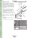
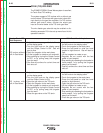
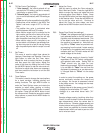
PREFLOW TIME
0 - 10 seconds
RUN-IN WFS:
Off, 50 to150 in/min.
Start Procedure
FUNCTION
Adjusts the time that shielding
gas
flows
after
the trigger
is
pulled and
prior to feeding wire.
Run-in sets the wire feed
speed from the time the trigger
is pulled until an arc is estab-
lished.
The Start Procedure is not
commonly used with STT
procedures.
PARAMETER
RANGE
Postflow Time:
0 to 10 seconds
FUNCTION
Adjusts the time that shielding
gas flows after the welding out-
put turns off.
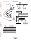
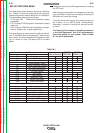
ELECTRODE AND GAS
STEEL CO
2
STAINLESS
Ar/CO
2
He/Ar/CO
2
STEEL CO
2
STAINLESS
Ar/CO
2
He/Ar/CO
2
WIRE SIZE
0.035 0.045 0.052
110 126 126
110 126 126
WELD MODES
START OPTIONS
END OPTIONS
ARC CONTROL
Steel
.035"
SET
SETUP
IR PORT
STT
WAVEFORM CONTROL TECHNOLOGY
WELD MODE
ARC CONTROL
109
START OPTIONS
END OPTIONS
STEEL CO
STEEL CO
STEEL AR/CO
STAINLESS He/Ar/CO
STAINLESS He/Ar/CO
STAINLESS Ar/CO
2
2
2
2
2
2
(with Hot Start)
(SYNERGIC STT)
SYNERGIC STT, OPEN ROOT
123 124 124
123 124 124
111 117 120
112 118 121
113 119 122
135 137 ---
127 129 ---
131 133 ---
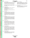
Burnback: 0 to .25
Seconds
The burnback time is the
amount of time that the weld
output continues after the wire
stops feeding. It prevents the
wire from sticking in the puddle
and prepares the end of the
wire for the next arc start.
Crater Procedur
e
Crater is not commonly used
in STT weld procedures.
MSP4 OPERATION