


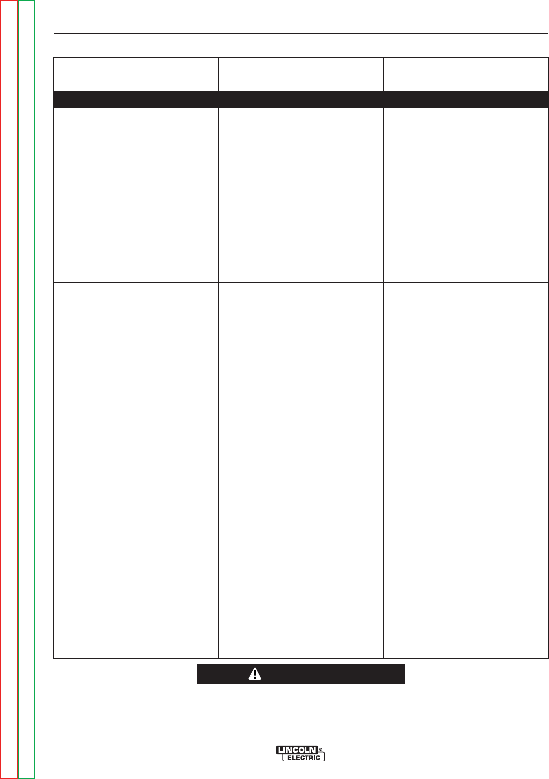
FUNCTION PROBLEMS
Observe Safety Guidelines detailed in the beginning of this manual.
PROBLEMS
(SYMPTOMS)
POSSIBLE AREAS OF
MISADJUSTMENT(S)
RECOMMENDED
COURSE OF ACTION
If for any reason you do not understand the test procedures or are unable to perform the tests/repairs safely,
contact the Lincoln Electric Service Department for technical troubleshooting assistance before you proceed.
Call 1-888-935-3877.
CAUTION
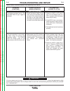
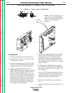
The displays are blank (not lit). The
wire feeds when the gun trigger is
activated.
1. Check for loose or faulty connec-
tions at plug on the display board,
to plug on the memory board to
the plug on the msp-4 board to
the plug on the push-pull daugh-
ter board to the feed head board.
1. Check for 5VDC at J37 pins 2
and 10 on the display board. If 5
VDC is present, then the display
board may be faulty.
2. If the 5VDC is low or not present,
check for loose or faulty connec-
tions in SPI circuit. See machine
schematic.
3. The feedhead control board may
be faulty.
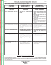
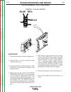
The dual procedure is not function-
al when using the remote Dual
Procedure switch. The STATUS
LEDs are steady green on the
power source, and wire drive units.
1. Make certain the LED indicator on
the Dual Procedure Panel is in the
middle position. This enables the
gun remote dual procedure
switch.
1. Check shielded cable lead and
connections from J86 on PC BD
to MSP panel. Check SPI cable
from MSP panel to Dual/memory
panel. Per machine schematic.
2. Check for 5VDC at J86 pins 2
and 10. Check for 15VDC at J86
pins 1 and 10. If voltage is not
present replace feed head. If
leads and voltages are good
replace dual/memory panel.
TROUBLESHOOTING AND REPAIR
F-10 F-10
POWER FEED® 25M
Return to Section TOC Return to Section TOC Return to Section TOC Return to Section TOC
Return to Master TOC Return to Master TOC Return to Master TOC Return to Master TOC