


INSTALLATION
A-9 A-9
POWER FEED® 25M
Return to Section TOC Return to Section TOC Return to Section TOC Return to Section TOC
Return to Master TOC Return to Master TOC Return to Master TOC Return to Master TOC
REMOTE SENSE LEAD SPECIFICATIONS
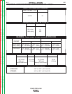
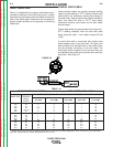
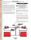
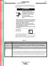
Welding with Multiple Arcs:
( See Figure A.7)
Special care must be taken when more than one arc is
welding simultaneously on a single part. Arc blow and
arc interference may occur or be magnified. Each
power source requires a work lead from the work stud
to the welding fixture. Do not combine all of the work
leads into one lead. Performing welding in the direction
away from the work leads. Connect all of the work
sense leads from each power source to the work piece
at the end of the weld, such that they are out of the
path of the weld current. See Figure A.7
For the best results when pulse welding, set the wire
size and wire feed speed the same for all the arcs.
When these parameters are identical, the pulsing fre-
quency will be the same, helping to stabilize the arcs.
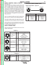
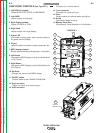
LOADING SPOOLS OF WIRE
• Keep hands, hair, clothing and tools
away from rotating equipment.
• Do not wear gloves when threading
wire or changing wire spool.
• Only qualified personnel should install,
use or service this equipment.
------------------------------------------------------------------------
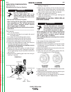
Loading 10 to 15 lb. (4.5 – 6.8kg) Spools.
A K468 spindle adapter is required for loading 2"
(51mm) wide spools on 2" (51mm) spindles. Use a
K468 spindle adapter for loading 2-1/2" (64mm) wide
spools.
1. Squeeze the release bar on the retaining collar and
remove it from the spindle.
2. Place the spindle adapter on the spindle, aligning
the spindle brake pin with the hole in the adapter.
3. Place the spool on the spindle and align the adapter
brake tab with one of the holes in the back side of
the spool. An indicator mark on the end of the spin-
dle shows the orientation of the brake tab. Be cer-
tain the wire feeds off of the spool in the proper
direction.
4. Re-install the retaining collar. Make sure that the
release bar snaps out and that the retaining collar
fully engages the groove on the spindle.
CCOONNNNEECCTT A A LLLL S SEENNSSEE
LLEEAADDSS A AT THT THEE E ENNDD
OOF THF THEE W WEELLDD
CCOONNNNEECCT AT A
LLLL
WWOORRKK LLEEAADD
SS A ATT
THTHEE B BEEGGINNINN
IINNG G
OFOF
THTHEE W WEELLDD
DDIREIRE
CCTIOTIONN
OF OF
TRTRAAVVEELL
FIGURE A.7
WARNING