


TROUBLESHOOTING
E-5 E-5
POWER FEED® 25M
Return to Section TOC Return to Section TOC Return to Section TOC Return to Section TOC
Return to Master TOC Return to Master TOC Return to Master TOC Return to Master TOC
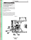
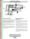
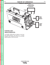
COMPONENT STATUS LIGHTS
Each network component has a single status light. The
light is a bicolor, Green/Red, LED. The purpose of the
status light is to allow the operator to quickly identify
that the system is working properly or, if not, which
component is causing the problem. By using the status
lights the operator can quickly pinpoint the system
problem to a particular component. See the following
table for a complete listing and description of all status
light conditions.
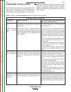
STATUS LIGHT STATES
NOTE: The green light ON and steady indicates a normal functioning system.
LED State
Off
Green LED blink-
ing at a “normal”
rate
Red LED blinking
at a “normal” rate
Red/Green LED
blinking at a “nor-
mal” rate
Power Source LED
Power Source is not turned ON or is not
function-
ing correctly.
It should only blink for a few seconds while
the system is mapping (identifying compo-
nents). If blinking continues every group may
have a mapping error. (DIP switches may be
set incorrectly).
Indicates a recoverable communication fault.
The power source should automatically
recover: If it cannot recover the LED will be
solid red.
Indicates a recoverable hardware fault such
as over temperature, overload shutdown etc.
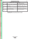
LED on any other nodes (components);
Wire Feeder, Control Box Etc.
The system component is not receiving input
power or
is faulty.
It should only blink for a few seconds until the
system component (node) has been recog-
nized. If the blinking continues at least one
node in the group has a mapping error (DIP
switches may be set incorrectly). The node or
nodes with mapping errors will be blinking
red.
• There may be too many components in the
group. All components in the group will be
blinking green.
• The power source bus may not be available.
The bus may be being used to program
another component.
• The LED’s of the power source and the
component being programmed will be solid
green.
Indicates a recoverable communication fault
most likely caused by one of the following.
• More than one control box (UI) in the group.
All control boxes in the group will be blinking
red.
• No control box (UI) in the group. All nodes in
the group will be blinking red.
• More than one node, of the same equip-
ment type, has the same group and feed
head (FH) numbers. All these nodes will be
blinking red.
• The feed head DIP switches may be set to
zero. The nodes with DIP switches set to zero
will be blinking red.
•The node bus may be off.
Indicates a recoverable hardware fault such
as over temperature, overload shutdown etc.
Could also be an open shutdown circuit at the
feed head (leads 570, 572 with tab terminals)
typically used for water flow shutdown switch-
es.