


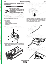

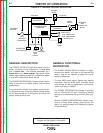
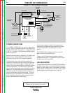
VOLTAGE
SENSE
LEAD #67A
LEAD #67
PUSH PULL
DAUGHTER
DRIVE
MOTOR
GEAR BOX
AND
CONDUCTOR
BLOCK
FEEDBACK
TACH
STATUS LED
GUN TIGGER AND
DUAL PROCEDURE
RECEPTACLE
2-STEP/
4-STEP
CONTROL BOARD
FEEDHEAD
DIP SWITCHES
TO POWER
SOURCE
INPUT
NETWORK
RECEPTACLE
HEATER LIGHT
CONNECTOR
FOOT AMPTROL
COLD
INCH/
GAS
PURGE
GAS
SOLENOID
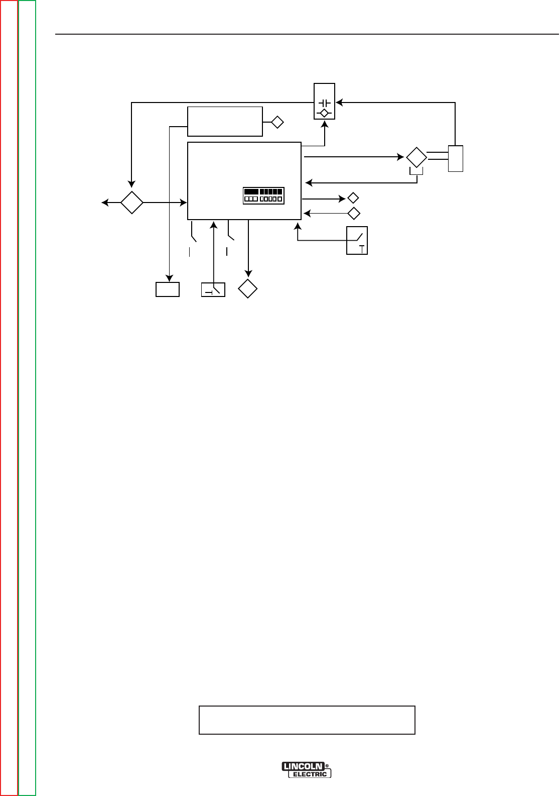
THEORY OF OPERATION
E-2 E-2
POWER FEED® 25M
Return to Section TOC Return to Section TOC Return to Section TOC Return to Section TOC
Return to Master TOC Return to Master TOC Return to Master TOC Return to Master TOC
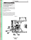
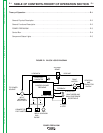
GENERAL DESCRIPTION
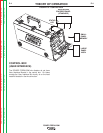
The POWER FEED® 25 Single Wire Feeder is a wire
feeder, consisting of two components - a wire drive
and a control box - are available assembled as a
bench unit or as a boom system. High speed, highly
reliable digital cables connect the components togeth-
er and to the Power Wave power source.
The POWER FEED® 25M Wire Feeder system has the
ability to connect to one power source, use the same
power source.
The powerful two roll wire drive system sets the indus-
try standard for ease of use. Its patented design allows
for tool-less change out of wire guides and drive rolls
greatly reducing set up time.
FIGURE E.2 - GENERAL PHYSICAL DESCRIPTION
GENERAL FUNCTIONAL
DESCRIPTION
• The POWER FEED® 25M Wire Feeder is a highly
versatile wire feeder with easy to use features that
make it easy for the operator to adjust the arc for
specific preferences.
• The new MSP4 panel clearly displays key welding
information. Use the MSP4 panel to quickly adjust
weld settings, arc starting parameters, arc end para-
meters and set-up variables.
• The POWER FEED® 25M Wire Feeder is provided
with an infrared red (IR) port. Transferring welding
settings is accomplished with a common palm com-
puter.
• When the POWER FEED® 25M Wire Feeder is cou-
pled to a Power Wave welding power source, the
result is a welding system with absolutely superior
arc performance.
NOTE: Unshaded areas of Block Logic
Diagram are the subject of discussion