


INSTALLATION
A-6 A-6
POWER FEED® 25M
Return to Section TOC Return to Section TOC Return to Section TOC Return to Section TOC
Return to Master TOC Return to Master TOC Return to Master TOC Return to Master TOC
SHIELDING GAS CONNECTION
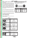
CYLINDER may explode if
damaged.
• Keep cylinder upright and
chained to support.
• Keep cylinder away from areas where it may be
damaged.
• Never lift welder with cylinder attached.
• Never allow welding electrode to touch cylinder.
• Keep cylinder away from welding or other live
electrical circuits.
• BUILD UP OF SHIELDING GAS MAY
HARM HEALTH OR KILL.
• Shut off shielding gas supply when not in
use.
• See American National Standard Z-49.1, "Safety
in Welding and Cutting” Published by the
American Welding Society.
------------------------------------------------------------------------
MAXIMUM INLET PRESSURE IS 100 PSI. (6.9 BAR.)
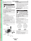
Install the shielding gas supply as follows:
1. Secure the cylinder to prevent it from falling.
2. Remove the cylinder cap. Inspect the cylinder valves
and regulator for damaged threads, dirt, dust, oil or
grease. Remove dust and dirt with a clean cloth. DO
NOT ATTACH THE REGULATOR IF OIL, GREASE OR
DAMAGE IS PRESENT! Inform your gas supplier of
this condition. Oil or grease in the presence of high
pressure oxygen is explosive.
3. Stand to one side away from the outlet and open the
cylinder valve for an instant. This blows away any dust
or dirt which may have accumulated in the valve outlet.
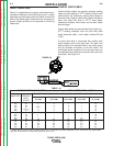
4. Attach the flow regulator to the cylinder valve and tight-
en the union nut(s) securely with a wrench. Note: if
connecting to 100% CO
2
cylinder, insert regulator
adapter between regulator and cylinder valve. If
adapter is equipped with a plastic washer, be sure it is
seated for connection to the CO
2
cylinder.
5. Attach one end of the inlet hose to the outlet fitting of
the flow regulator. Attach the other end to the welding
system shielding gas inlet. Tighten the union nuts with
a wrench.
6. Before opening the cylinder valve, turn the regulator
adjusting knob counterclockwise until the adjusting
spring pressure is released.
7. Standing to one side, open the cylinder valve slowly a
fraction of a turn. When the cylinder pressure gage
stops moving, open the valve fully.
8. The flow regulator is adjustable. Adjust it to the flow rate
recommended for the procedure and process being
used before making a weld.
WARNING
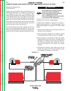
ELECTRODE POLARITY
The wire feeder is factory set for Electrode Positive
welding. Most GMAW welding procedures use
Electrode Positive welding. Most GTAW and some
Innershield procedures use Electrode Negative weld-
ing.
When changing the electrode polarity, the weld
cables must be changed at the power source studs
and the DIP switch inside the wire feeder must be
properly set. Operation with the DIP switch in the
wrong position will cause erratic arc performance.
ELECTRIC SHOCK CAN KILL.
• Turn the input power OFF at the weld-
ing power source before changing
electrode polarity.
• Do not touch electrically live parts.
• Only qualified personnel should per-
form maintenance work.
-------------------------------------------------------------------------
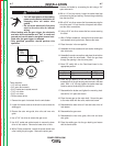
Electrode Polarity DIP switch #7 setting
Positive OFF (Factory setting)
Negative ON
Tools required:
• 5/16" nut driver
To change the DIP switch from Electrode Polarity:
1. Turn power off at the welding power source
2. Remove the spool of wire from the feeder.
3. Remove the 4 screws holding the cover. Lift the cover
out of the feeder.
4. Move DIP switch #7 on the feed head board to the
appropriate position.
5. Install the cover and secure with the screws.
CAUTION
WARNING