


OPERATION
B-10 B-10
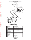
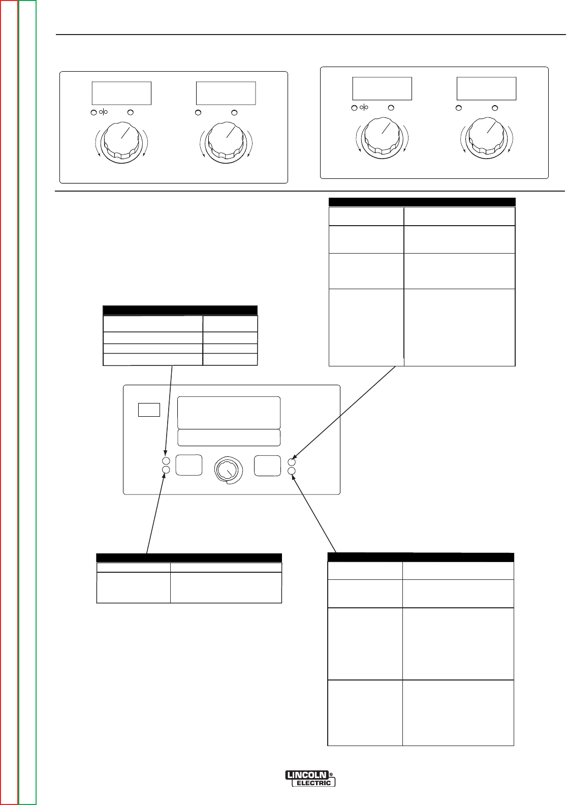
POWER FEED® 25M
Return to Section TOC Return to Section TOC Return to Section TOC Return to Section TOC
Return to Master TOC Return to Master TOC Return to Master TOC Return to Master TOC
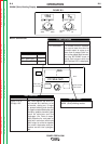
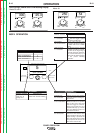
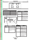
300
25.3
WFS AMPS
VOLTS TRIM
Less
WFS
Less
Volts
More
Volts
More
WFS
250
54
W
FS AMPS
VOLTS TRIM
Less
WFS
S
horter
Arc
L
onger
Arc
More
WFS
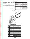
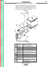
START OPTIONS
E
ND OPTIONS
SET
SETUP
I
R PORT
STD CV MIG
WAVEFORM CONTROL TECHNOLOGY
WELD MODE
ARC CONTROL
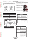
5
EFFECT / RANGE
Postflow Time
0 to 10 seconds
Crater Procedure
0 TO 10.0 SECONDS
Burnback:
0 to .25 Seconds
DESCRIPTION
Adjusts the time that shielding
gas flows after the welding out-
put turns off.
Crater Procedure controls the
WFS and Volts for a specified
time at the end of the weld
after the trigger is released.
During the Crater time, the
machine will ramp up or down
from the Weld Procedure to
the Crater Procedure.
The burnback time is the
amount of time that the weld
output continues after the wire
stops feeding. It prevents the
wire from sticking in the puddle
and prepares the end of the
wire for the next arc start.
PROCESS
GMAW, STANDARD CV
GMAW, POWER MODE
FCAW, STANDARD CV
WELD MODE
5
40
6
ARC CONTROL
W
ELD MODE
END OPTIONS
S
TART OPTIONS
DESCRIPTION
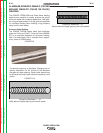
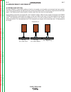
Pinch controls the arc characte-
-ristics when short-arc welding.
EFFECT / RANGE
(Soft)-10.0 to
(Crisp)+10.
PINCH
0
EFFECT / RANGE
P
reflow Time
0
- 10 seconds
Run-In WFS:
Off, 50 to150 in/min.
S
tart Procedure
0 - 10 seconds
DESCRIPTION
A
djusts
the
t
ime
t
hat
shielding
gas
f
lows
after the trigger is
p
ulled
a
nd
prior to feeding wire.
R
un-In sets the wire feed
s
peed from the time the trigger
is pulled until an arc is estab-
lished.
The Start Procedure controls
t
he WFS and Volts for a speci-
fied time at the beginning of
the weld. During the start time,
the machine will ramp up or
down from the Start Procedure
to the preset Welding
Procedure.
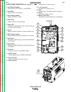
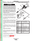
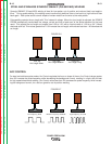
Non-Synergic GMAW and FCAW Welding Display
Modes 5 and 6:
Mode 40:
MSP4 OPERATION