


14
2
5
6
3
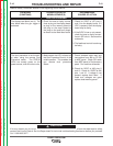
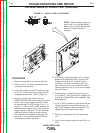
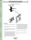
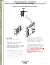
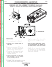
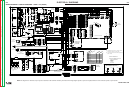
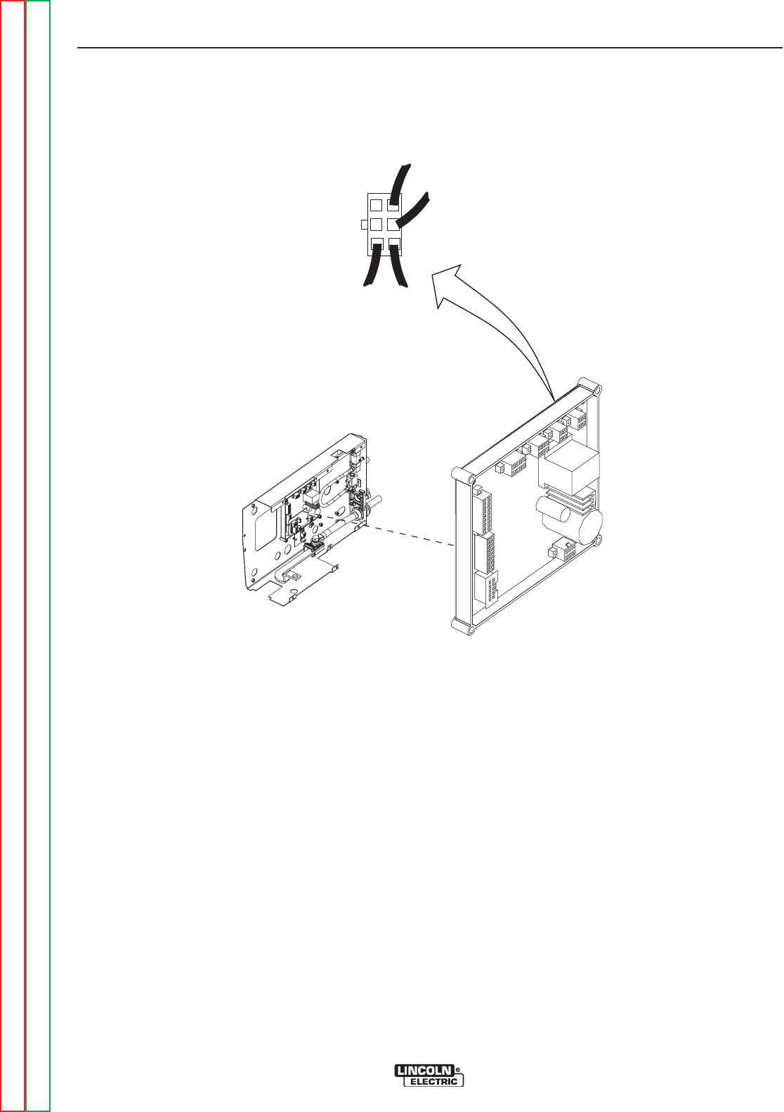
#550
#551
FIGURE F.3 – QUICK CONNECTOR #550 AND #551 LOCATIONS
DRIVE MOTOR TEST (continued)
PROCEDURE
1. Remove input power to wire feed unit.
2. Using the 3/8 in. nut driver, remove the
cover from the wire feeder.
3. Locate the two quick connectors in the two
motor armature leads. Refer to Figure F.3.
Do NOT disconnect the leads.
4. Apply the correct input power (from the
POWER FEED® 25M control cable) to the
wire feeder. Activate the gun trigger and
with the motor running check at the quick
connectors [#550 White (+) to #551 / Black
(-)] for approximately 1 VDC to 32 VDC
dependent upon motor speed. The motor
speed should vary with changes in motor
armature voltage.
5. If the correct voltages are NOT present at
the motor leads, check the associated
leads between the motor and plug J83 on
the feedhead board. If the leads are OK,
the feedhead board may be faulty.
6. If the correct voltages are present at motor
armature leads and the motor does not run
and vary speed with changes in armature
voltage, the motor or gear box may be
faulty. See Gear Box and Drive Motor
Removal and Replacement.
7. Install the wire feeder cover using the 3/8
in. nut driver.
TROUBLESHOOTING AND REPAIR
F-18 F-18
POWER FEED® 25M
Return to Section TOC Return to Section TOC Return to Section TOC Return to Section TOC
Return to Master TOC Return to Master TOC Return to Master TOC Return to Master TOC