


23
4
5
2
J1
J2
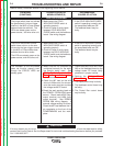
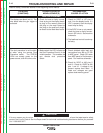
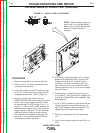
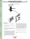
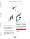
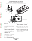
FIGURE F.1 – PLUG J1 AND J2 LOCATIONS
VOLTAGE SENSE PC BOARD TEST (continued)
PROCEDURE
1. Remove input power from the wire feed unit.
2. Using the 3/8 in. nut driver, remove the cover
from behind the wire reel.
3. Locate the voltage sense PC board and plugs
J1 and J2. Do not remove the plugs from the
voltage sense pc board. Refer to Figure F.1.
4. Apply the correct input power (from the
POWER FEED® 25M control cable) to the wire
feeder. With the gun trigger activated, check
for approximately 12 VDC at plug J1 pin 1 (+)
to pin 4 (-). If the 12 VDC is NOT present, the
feedhead board may be faulty. Also check for
trigger closure at J85 pins 1 & 2 on feedhead
board and loose or faulty wires and connec-
tions between the feedhead board (plug J85
and plug J1 on the voltage sense PC board.
This voltage is polarity sensitive.
5. With the gun trigger activated and arc voltage
present at the conductor block, check for arc
voltage from plug J1 pin 3 (lead 67) to the
workpiece. If actual arc voltage is NOT pre-
sent, check the continuity of lead 67 from the
conductor block to plug J1 pin 3 on the voltage
sense PC board.
6. If the actual arc voltage IS present at plug J1
pin 3 (lead 67), then check for arc voltage from
plug J2 pin 2 (lead 67B) to the workpiece. See
wiring diagram.
7. If the 12 VDC IS present in step #4 and the arc
voltage IS present in step #5 but the arc volt-
age is NOT present in step #6 (lead 67A), the
voltage sense PC board may be faulty.
8. Remove all input power from the wire feeder
unit.
9. Install the wire feeder cover with the 3/8 in. nut
driver.
TROUBLESHOOTING AND REPAIR
F-14 F-14
POWER FEED® 25M
Return to Section TOC Return to Section TOC Return to Section TOC Return to Section TOC
Return to Master TOC Return to Master TOC Return to Master TOC Return to Master TOC
NOTE: Inspect the molex plug con-
nector pins on the Voltage Sense
Board. If any of them are gold plat-
ed the P.C. board should be
replaced.