


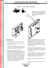
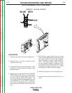
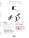
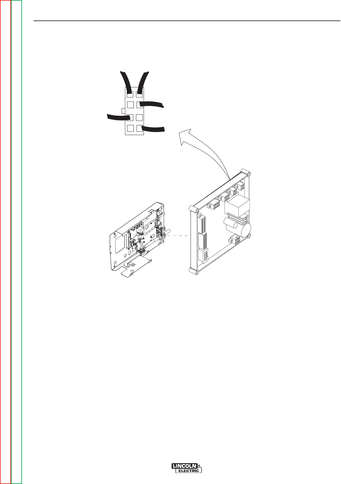
BLUE
Black
RED
J84
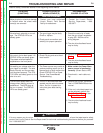
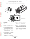
FIGURE F.2 – PLUG J84 LOCATION
TACH FEEDBACK TEST (continued)
TROUBLESHOOTING AND REPAIR
F-16 F-16
POWER FEED® 25M
Return to Section TOC Return to Section TOC Return to Section TOC Return to Section TOC
Return to Master TOC Return to Master TOC Return to Master TOC Return to Master TOC
PROCEDURE
1. Remove input power from the wire feeder unit.
2. Using the 3/8 in. nut driver, remove the cover
from behind wire reel.
3. Locate plug J84 on the feed head board. Refer
to Figure F.2. Do Not remove the plug from the
feed head board.
4. Apply the correct input power (from the POWER
FEED® 25M control cable) to the wire feeder
unit and check for approximately 5VDC from
(red wire) positive to (black wire) negative. This
is the supply voltage from feedhead board to the
tach feedback unit. If the 5VDC is missing or
not correct, the feedhead board may be faulty.
Also check for loose or faulty wires and connec-
tions.
5. With the gun trigger activated and the motor
running, check the feedback voltage at plug J84
(blue wire) positive to (black wire) negative.
Normal feedback voltage is approximately 2
VDC. If the correct supply voltage is present
and the feedback voltage is missing, the tach
unit may be faulty. With the motor NOT running,
the feedback voltage may be either 0 or 5 VDC
depending upon where the motor stopped.
6. Remove input power from the wire feeder unit.
7. Install the wire feeder cover with the 3/8 in. nut
driver.