


MAINTENANCE
D-2 D-2
POWER FEED® 25M
Return to Section TOC Return to Section TOC Return to Section TOC Return to Section TOC
Return to Master TOC Return to Master TOC Return to Master TOC Return to Master TOC
ELECTRIC SHOCK can kill.
• Do not operate with covers
removed.
• Turn off power source before
installing or servicing.
• Do not touch electrically hot
parts.
• Turn the input power to the welding power
source off at the fuse box before working in the
terminal strip.
• Only qualified personnel should install, use or
service this equipment.
WARNING
SAFETY PRECAUTIONS
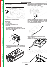
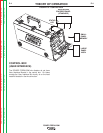
ROUTINE MAINTENANCE
• Check weld cables, control cables and gas hoses for cuts.
• Clean and tighten all weld terminals.
PERIODIC MAINTENANCE
• Clean drive rolls and inner wire guide and replace if worn.
• Blow out or vacuum the inside of the feeder.
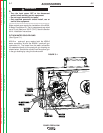
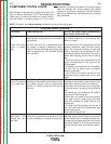
CALIBRATION SPECIFICATION
All calibrations are factory set on the POWER FEED® 25M.
To verify the wire feed speed:
• Assemble a .045 (1.2mm) drive roll kit into the POWER FEED® 25M.
• Load a spool of .045 (1.2mm) electrode and thread the electrode
through the wire drive.
• Adjust the wire feed speed to 300 in/min (7.62m/min).
• Press the COLD FEED switch and measure the actual wire feed
speed with a calibrated wire feed speed tachometer.
• The measured wire feed speed should be within 2% of the set value.
• If no feed speed meter is available, cut the wire at gun tip. Cold inch
for 5 seconds at 300 inches/minute. Measure the wire - should be 24
inches +1, -2 inches.
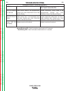
To verify the voltage display:
• Set the welding power source and POWER FEED® 25M to a CV pro-
cedure that gives steady "spray" transfer in the arc.
• While a weld is being made, measure the voltage from the feed plate
to work with a calibrated volt meter.
• The displayed voltage on the POWER FEED® 25M should be within
2% of the measured value.