


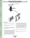
THUMB THUMB
S
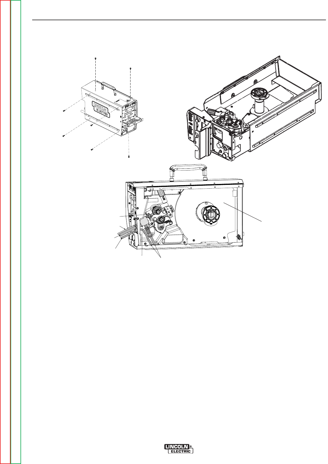
CREWSCREW
CONDUITCONDUIT
E
LECTRODEELECTRODE
CABLECABLE
G
UNGUN
BUSHINGBUSHING
WATERWATER
HOSESHOSES
WATERWATER
HOSEHOSE
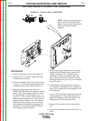
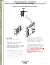
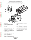
FIGURE F.4 – GEAR BOX AND DRIVE MOTOR REMOVAL AND REPLACEMENT
GEAR BOX REMOVAL AND DRIVE MOTOR
REMOVAL AND REPLACEMENT PROCEDURE (continued)
TROUBLESHOOTING AND REPAIR
F-20 F-20
POWER FEED® 25M
Return to Section TOC Return to Section TOC Return to Section TOC Return to Section TOC
Return to Master TOC Return to Master TOC Return to Master TOC Return to Master TOC
PROCEDURE
1. Remove input power to wire feed unit.
2. Using the 3/8 in. nutdriver, remove the
case cover.
3. Locate and remove plug J84 from the
feedhead - control board, located under
control box cover Refer to figure F.4.
4. Thread plug J84 and associated leads
through the vertical baffle. Cut any
necessary cable ties.
5. Locate and disconnect the motor leads
(#551 and #550) at the quick connects.
Cut any necessary cable ties.
6. Using the Phillips head screwdriver, remove
the #67 lead from the conductor block.
7. Using the needlenose pliers, disconnect the
gas hose from the brass gun connector
block.
8. Using the 7/16 in. socket wrench, remove
the four mounting bolts, lock washers, and
flat washers from the plastic base insulator.
9. Carefully slide and remove the entire gear
box, drive motor, and wire drive assembly
from the wire feeder case. Note insulation
placement for reassembly.
Control Box Cover