


FX Series Programmable Controllers Devices in Detail 4
4-31
4.12.1 General Use Registers
Data registers, as the name suggests, store data. The stored data can be interpreted as a
numerical value or as a series of bits, being either ON or OFF.
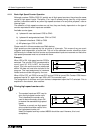
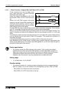
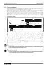
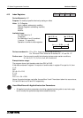
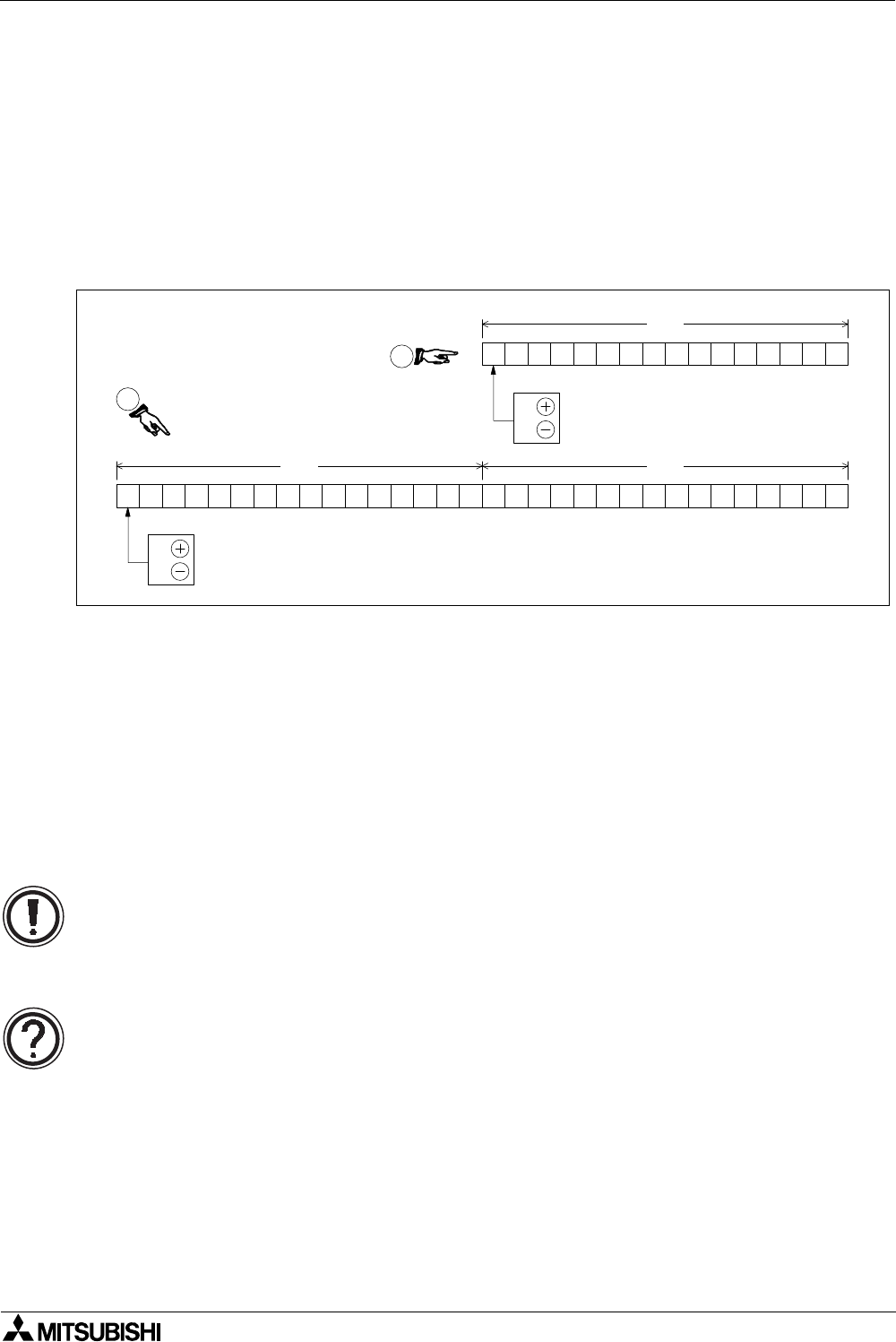
A single data register contains 16bits or one word. However, two consecutive data registers
can be used to form a 32bit device more commonly known as a double word.
If the contents of the data register is being considered numerically then the Most Significant Bit
(MSB) is used to indicate if the data has a positive or negative bias. As bit devices can only be
ON or OFF, 1 or 0 the MSB convention used is, 0 is equal to a positive number and 1 is equal
to a negative number.
The diagram above shows both single and double register configurations. In the diagram, at
point ➁, it should be noted that the ‘lower’ register D0 no longer has a ‘Most Significant Bit’.
This is because it is now being considered as part of a 32bit-double word. The MSB will always
be found in the higher 16 bits, i.e. in this case D1. When specifying a 32 bit data register within
a program instruction, the lower device is always used e.g. if the above example was to be
written as a 32bit instructional operand it would be identified as D0. The second register, D1,
would automatically be associated.
Once the data is written to a general data register, it remains unchanged until it is overwritten.
When the PLC is turned from RUN to STOP all of the general data registers have their current
contents overwritten with a 0 (zero).
Data retention:
• Data can be retained in the general use registers when the PLC is switched from RUN to
STOP if special auxiliary relay M8033 is ON.
Data register updates:
• Writing a new data value to a data register will result in the data register being updated
with the new data value at the end of the current program scan.
D1 D0
D0
0:
1:
0:
1:
2
1
MSB - Most Significant Bit
MSB - Most Significant Bit