


FX Series Programmable Controllers Devices in Detail 4
4-24
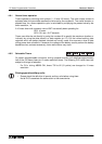
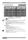
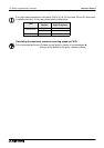
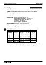
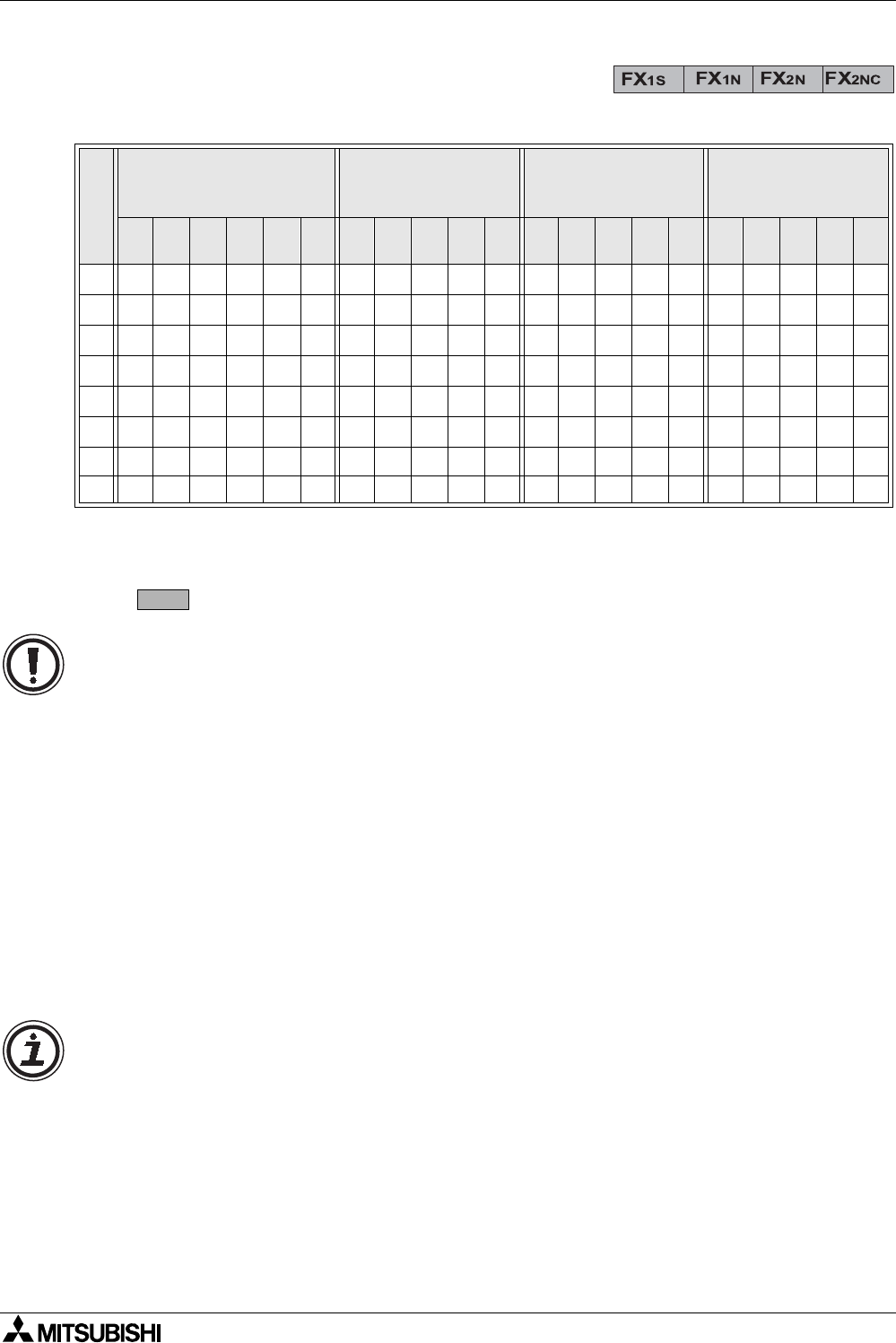
4.11.2 Availability of High Speed Counters
The following device table outlines the
range of available high speed counters.
Key: U - up counter input D - down counter input
R - reset counter (input) S - start counter (input)
A - A phase counter input B - B phase counter input
- Counter is backed up/latched
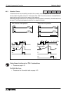
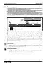
Input assignment:
• X6 and X7 are also high speed inputs, but function only as start signals. They cannot be
used as the counted inputs for high speed counters.
• Different types of counters can be used at the same time but their inputs must not
coincide. For example, if counter C247 is used, then the following counters and
instructions cannot be used;
C235, C236, C237, C241, C242, C244, C245, C246, C249, C251, C252, C254, I0❏❏,
I1❏❏, I2❏❏.
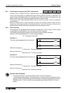
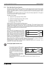
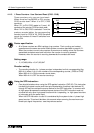
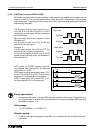
Counter Speeds:
• General counting frequencies:
- Single phase and bi-directional counters; up to 10 kHz.
- A/B phase counters; up to 5 kHz.
- Maximum total counting frequency (A/B phase counter count twice)
FX
1S & FX1N 60kHz, FX2N & FX2NC 20kHZ.
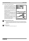
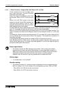
• For FX
2N & FX2NC Inputs X0 and X1 are equipped with special hardware that allows
higher speed counting as follows:
- Single phase or bi-directional counting (depending on unit) with C235, C236 or C246;
up to 60 kHz.
- Two phase counting with C251; up to 30 kHz.
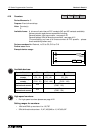
I
N
P
U
T
1 Phase counter
user start/reset
1 Phase counter
assigned
start/reset
2 Phase counter
bi-directional
A/B Phase counter
C235
C236
C237
C238
C239
C240
C241
C242
C243
C244
C245
C246
C247
C248
C249
C250
C251
C252
C253
C254
C255
X0
U/D U/D U/D U U U A A A
X1
U/D R RDDDBBB
X2
U/D U/D U/D R R R R
X3
U/D R S R U U A A
X4
U/D U/D D D B B
X5
U/D R R R R R
X6 SSS
X7 SSS
C235