FX Series Programmable Controllers STL Programming 3
3-7
3.5 Rules and Techniques For STL programs
It can be seen that there are a lot of advantages to using STL style programming but there are
a few points a user must be aware of when writing the STL sub-programs.
These are highlighted in this section.
3.5.1 Basic Notes On The Behavior Of STL programs
• When an STL state becomes active its program is processed until the next step is triggered.
The contents of the program can contain all of the programming items and features of a
standard ladder program, i.e. LoaD, AND OR, OUT, ReSeT etc., as well as applied
instructions.
• When writing the sub-program of an STL state, the first vertical ‘bus bar’ after the STL
instruction can be considered in a similar manner as the left hand bus bar of a standard
ladder program.
• In normal programming using dual coils is not an acceptable technique. However repetition
of a coil in separate STL program blocks is allowed.
STL
S005
Y000
Y011
Y014
RET
X001
X000
X012
X013
1
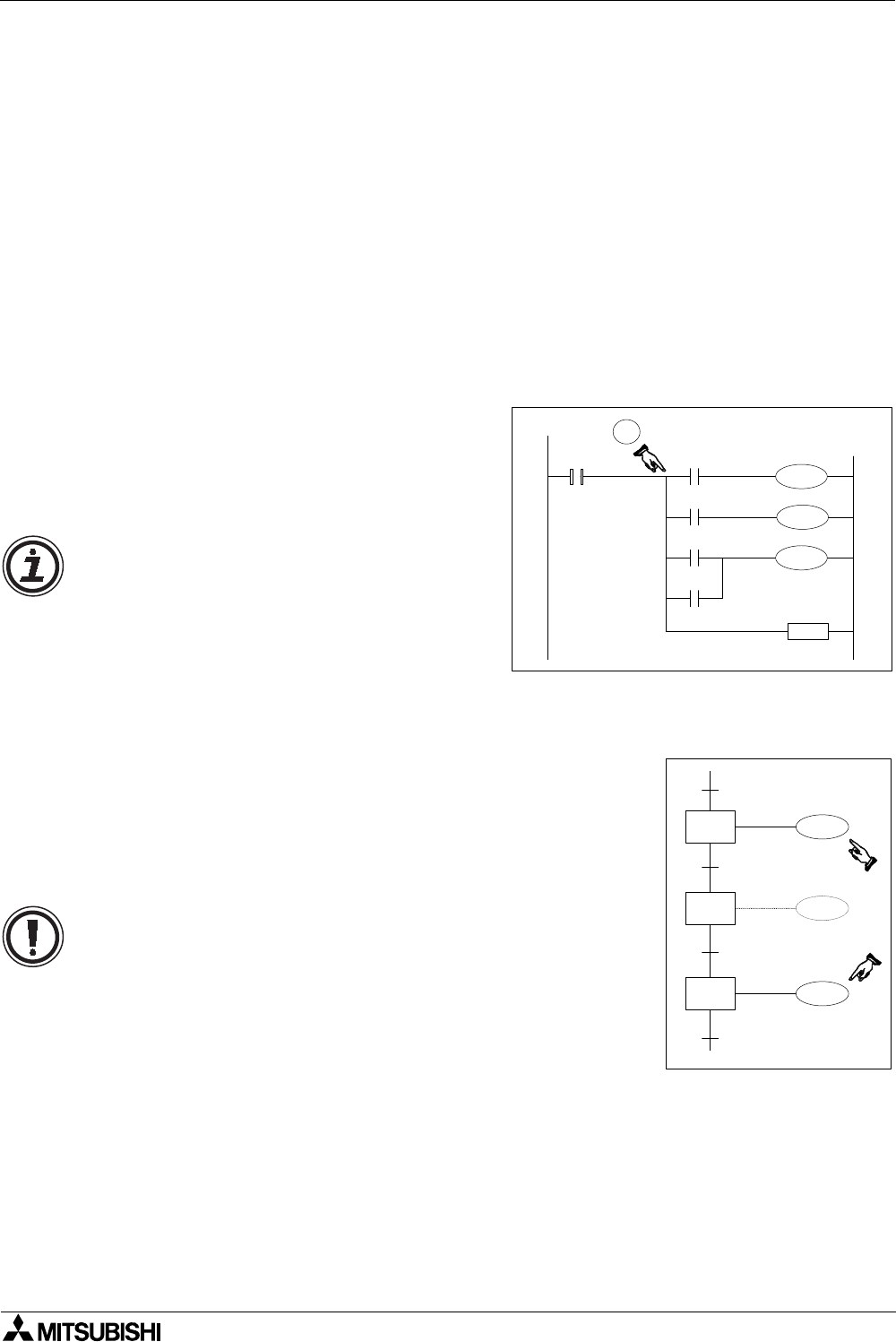
Each STL step makes its own bus bar. This
means that a user, cannot use an MPS
instruction directly after the STL instruction
(see ), i.e. There needs to be at least a
single contact before the MPS instruction.
Note: Using out coils and even applied
instructions immediately after an STL
instruction is permitted.
M111
S 30
S 31
S 32
M111
M112
This is because the user can take advantage of the STL’s
unique feature of isolating all STL steps except the active
STL steps.
This means in practice that there will be no conflict between
dual coils. The example opposite shows M111 used twice in a
single STL flow.
Caution: The same coil should NOT be programmed in steps
that will be active at the same time as this will result in the
same problem as other dual coils.


