


FX Series Programmable Controllers Devices in Detail 4
4-41
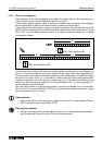
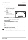
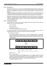
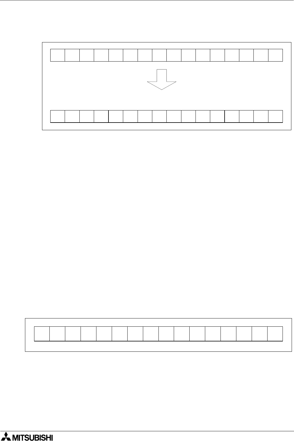
c) ABCD conversion
Using the original bit pattern as a base but adding the following BCD headers allows the
conversion of the binary data into a BCD format.
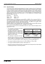
Binary Coded Decimal value= ERROR!!!!!
It will be noticed that this will produce an ERROR. The conversion will not be correct.
This is because BCD numbers can only have values from 0 to 9, but the second block of
4 bit devices from the left would have a value of 14. Hence, the error.
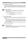
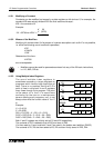
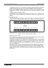
The conversion process is very similar to that of hexadecimal except for the mentioned
limit on values of 0 to 9. If the other blocks were converted just as an example the
following values would be found;
Extreme Left Hand Block= ((1
×
8) + (1
×
1)) = 9
Second Right Hand Block= ((1
×
4) + (1
×
2) + (1
×
1)) = 7
Extreme Right Hand Block= ((1
×
4) + (1
×
1)) = 5
BCD data is read from left to right as a normal number would be read. Therefore, in this
example the “9” would actually represent “9000”. The second right hand block is actually
“70” not “7”. The units are provided by the extreme right hand block, i.e. 5. The hundreds
“100’s” would have been provided by the second left hand block (which is in error).
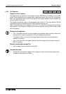
It is also important to note that there is no sign with BCD converted data. The maximum
number allowable for a single data word is “9999” and the minimum is “0000”.
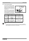
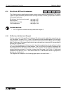
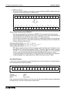
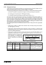
Word Data Summary
In each of the previous cases the original bit pattern had a further meaning. To recap the three
new readings and the original bit pattern,
Decimal : -24971
Hexadecimal : 9E75
BCD : Error (9?75)
Each meaning is radically different from the next yet they are all different ways of describing
the same thing. They are in fact all equal to each other!
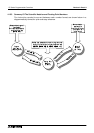
1 0 0 1 1 1 1 0 0 1 1 1 0 1 0 1
8421842184218421
1 0 0 1 1 1 1 0 0 1 1 1 0 1 0 1
1 0 0 1 1 1 1 0 0 1 1 1 0 1 0 1