


FX Series Programmable Controllers Basic Program Instructions 2
2-20
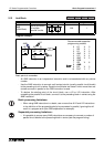
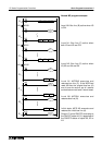
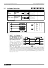
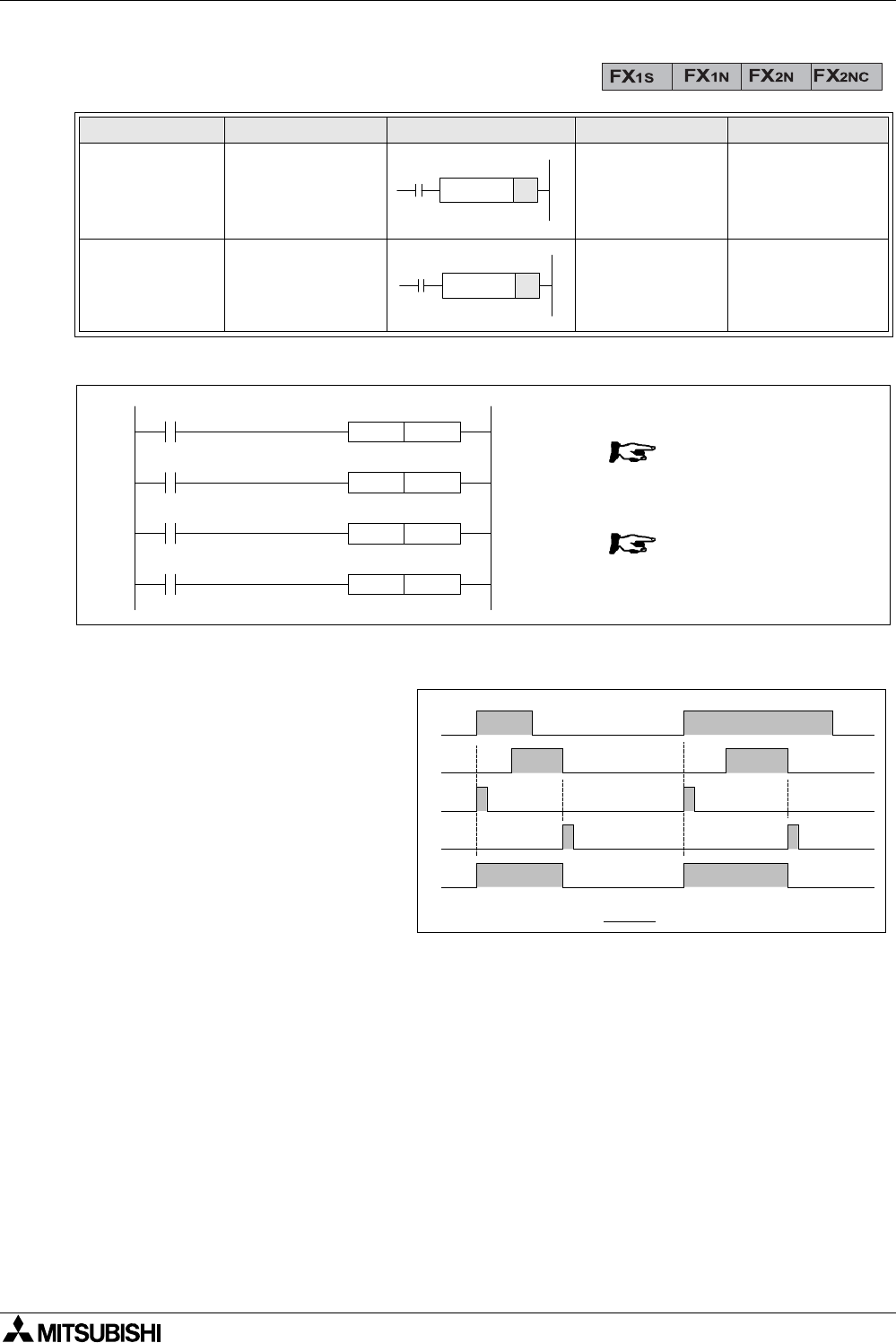
2.17 Leading and Trailing Pulse
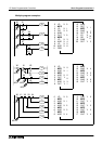
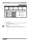
Program example:
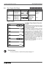
Basic points to remember:
- When a PLS instruction is
executed, object devices Y
and M operate for one
operation cycle after the drive
input signal has turned ON.
- When a PLF instruction is
executed, object devices Y
and M operate for one
operation cycle after the drive
input signal has turned OFF.
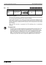
- When the PLC status is
changed from RUN to STOP and back to RUN with the input signals still ON, PLS M0 is
operated again. However, if an M coil which is battery backed (latched) was used instead
of M0 it would not re-activate. For the battery backed device to be re-pulsed, its driving
input (ex. X0) must be switched OFF during the RUN/STOP/RUN sequence before it will
be pulsed once more.
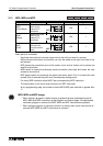
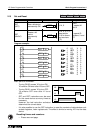
Mnemonic Function Format Devices Program steps
PLS
(PuLSe)
Rising edge
pulse
Y, M
(no special M
coils allowed)
2
PLF
(PuLse Falling)
Falling / trailing
edge pulse
Y, M
(no special M
coils allowed)
2
PLS
PLF
X0
PLS M0
M0
SET Y0
X1
PLF M1
M1
RST Y0
0
0
0
1
1
1
0
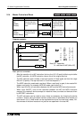
LD
PLS
LD
SET
LD
RST
PLF
LD
0
1
4
5
8
9
6
3
0
X
M
M
M
Y
M
Y
X
X0
X1
M0
M1
Y0
t msec