


FX Series Programmable Controllers Basic Program Instructions 2
2-15
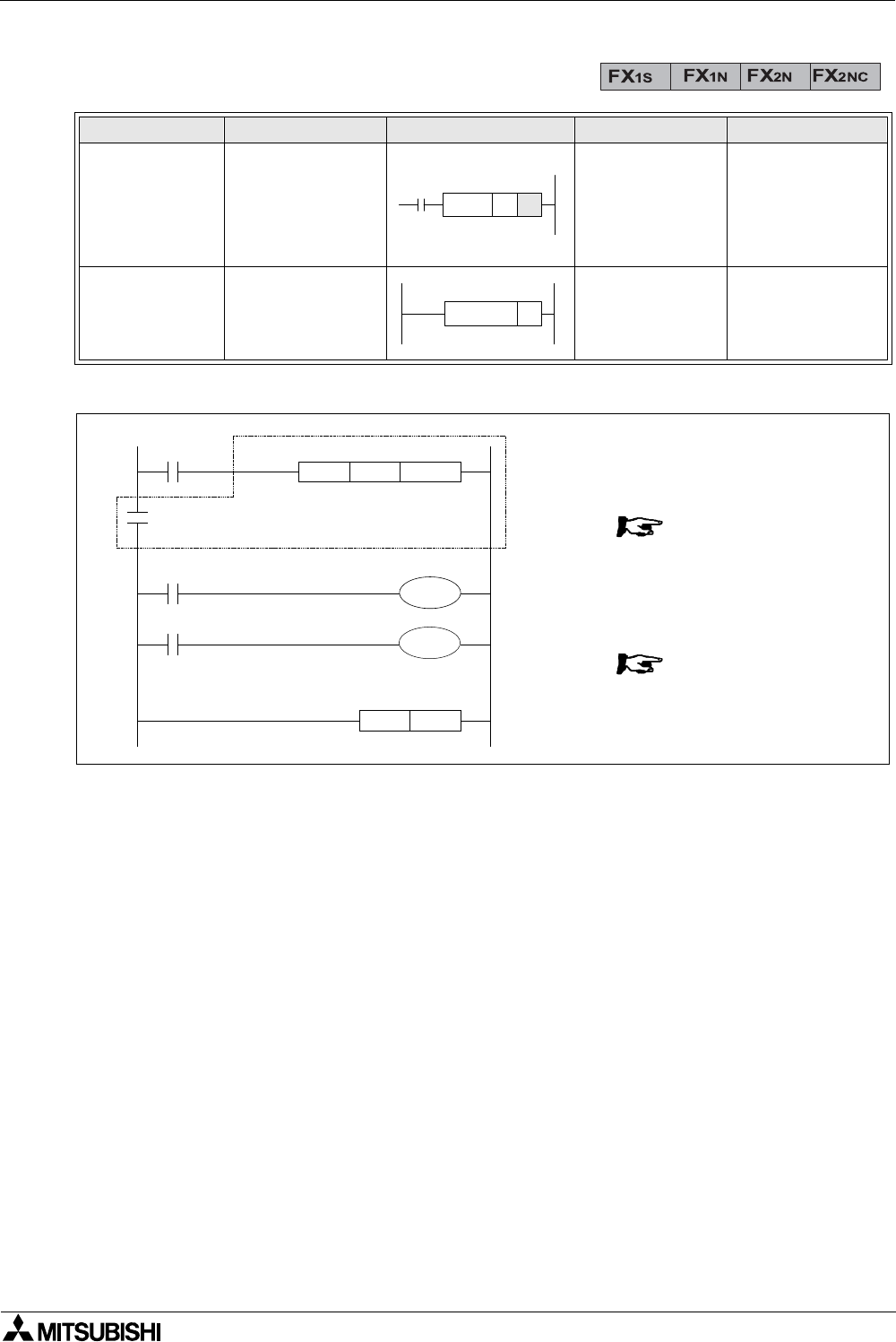
2.14 Master Control and Reset
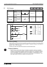
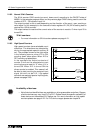
Program example:
Basic points to remember:
- After the execution of an MC instruction, the bus line (LD, LDI point) shifts to a point after
the MC instruction. An MCR instruction returns this to the original bus line.
- The MC instruction also includes a nest level pointer N. Nest levels are from the range
N0 to N7 (8 points). The top nest level is ‘0’ and the deepest is ‘7’.
- The MCR instruction resets each nest level. When a nest level is reset, it also resets ALL
deeper nest levels. For example, MCR N5 resets nest levels 5 to 7.
- When input X0=ON, all instructions between the MC and the MCR instruction execute.
- When input X0=OFF, none of the instruction between the MC and MCR instruction
execute; this resets all devices except for retentive timers, counters and devices driven
by SET/RST instructions.
- The MC instruction can be used as many times as necessary, by changing the device
number Y and M. Using the same device number twice is processed as a double coil
(see section 2.5.2). Nest levels can be duplicated but when the nest level resets, ALL
occurrences of that level reset and not just the one specified in the local MC.
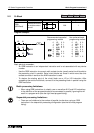
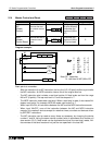
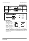
Mnemonic Function Format Devices Program steps
MC
(Master
Control)
Denotes the start
of a master control
block
Y, M (no special
M coils allowed)
N denotes the
nest level (N0 to
N7)
3
MCR
(Master
Control Reset)
Denotes the end of
a master control
block
N denotes the
nest level (N0 to
N7) to be reset.
2
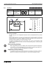
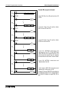
MC N
MCR N
X0
X1
M100N0MC
X2
N0MCR
M100N0
X
N
M
X
Y
X
Y
N
0
0
100
1
0
2
1
0
LD
MC
SP
LD
OUT
MCR
LD
OUT
0
1
4
5
7
8
6
Note: SP - space key
N - nest level of MC (N0 to N7)
Y1
Y0