


FX Series Programmable Controllers STL Programming 3
3-13
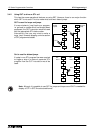
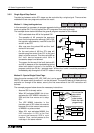
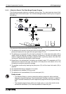
When a group of branch flows are activated, the user will often either;
a) ‘Race’ each flow against its counter parts. The flow which completes fastest would then
activate a joining function (“First State Merge” described in the previous section) OR
b) The STL flow will not continue until ALL branch flows have completed there tasks.
This is called a ‘Multiple State Merge”.
An explanation of Multiple State Merge now follows below.
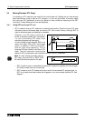
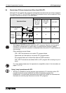
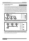
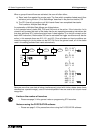
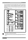
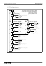
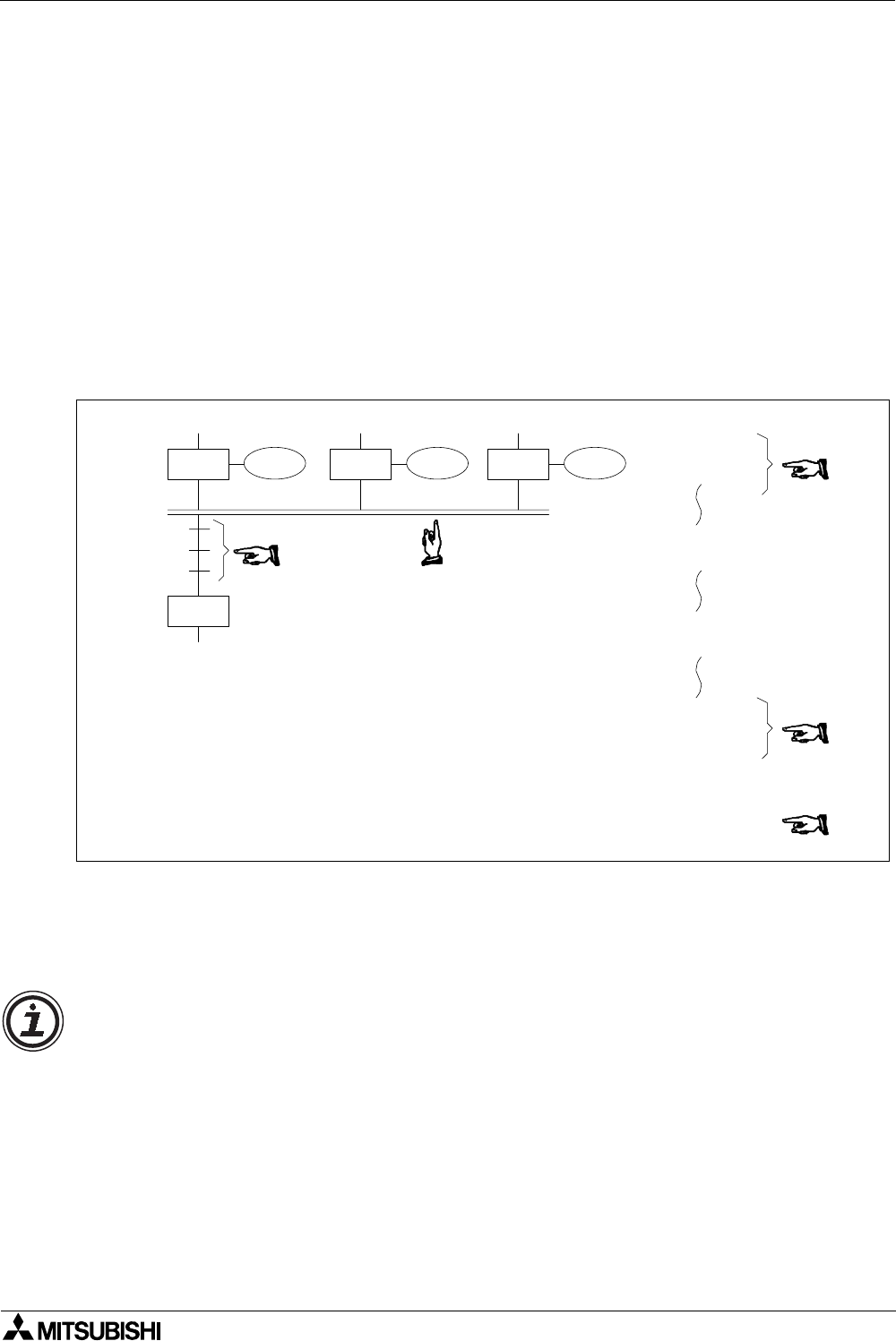
In the example below, states S29, S39 and S49 must all be active. If the instruction list is
viewed it can be seen that each of the states has its own operating/processing instructions but
that also additional STL instructions have been linked together (in a similar concept as the
basic AND instruction). Before state S50 can be activated the trigger conditions must also be
active, in this example these are X10, X11 and X12. Once all states and input conditions are
made the merging or joining state can be SET ON. As is the general case, all of the states
used in the setting procedure are reset automatically.
Because more than one state is being simultaneously joined with further states (some times
described as a parallel merge), a set of horizontal parallel lines are used to aid a quick visual
recognition.
Y10
S 29
S 39 S 49Y11 Y12
S 50
STL
OUT
S
Y
39
11
STL
OUT
S
Y
49
12
STL
OUT
S
Y
29
10
X10
X11
X12
STL
STL
STL
LD
AND
AND
SET
S
S
S
X
X
X
S
29
39
49
10
11
12
50
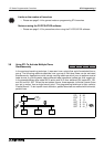
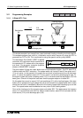
Limits on the number of branches
• Please see page 3-14 for general notes on programming STL branches.
Notes on using the FX-PCS/AT-EE software
• Please see page 3-15 for precautions when using the FX-PCS-AT/EE software.