FX Series Programmable Controllers Basic Program Instructions 2
2-8
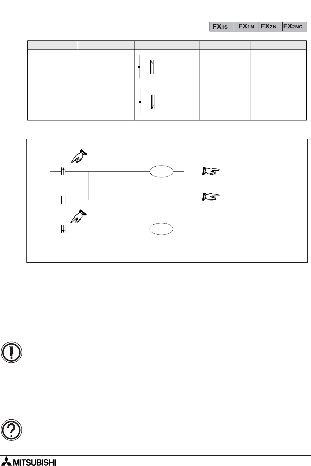
2.8 Load Pulse, Load Trailing Pulse
Program example:
Basic points to remember:
- Connect the LDP and LDF instructions directly to the left hand bus bar.
- Or use LDP and LDF instructions to define a new block of program when using the ORB
and ANB instructions (see later sections).
- LDP is active for one program scan after the associated device switches from OFF to ON.
- LDF is active for one program scan after the associated device switches from ON to
OFF.
Mnemonic Function Format Devices Program steps
LDP
(LoaDPulse)
Initial logical
operation -
Rising edge
pulse
X, Y, M, S, T, C 2
LDF
(LoaD Falling
pulse)
Initial logical
operation Falling
/ trailing edge
pulse
X, Y, M, S, T, C 2
LDF
LDP
X0
Y0
M100
X1
X0
0LDP X 0
2OR X 1
3 OUT M 100
4LDF X 0
6 OUT Y 0
Single Operation flags M2800 to M3071:
• The pulse operation instructions, when used with auxiliary relays M2800 to M3071,
only activate the first instruction encountered in the program scan, after the point in
the program where the device changes. Any other pulse operation instructions will
remain inactive.
• This is useful for use in STL programs (see chapter 3) to perform single step
operation using a single device.
• Any other instructions (LD, AND, OR, etc.) will operate as expected.
For more details please see page 4-5.


