


FX Series Programmable Controllers STL Programming 3
3-3
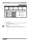
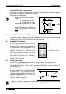
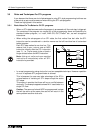
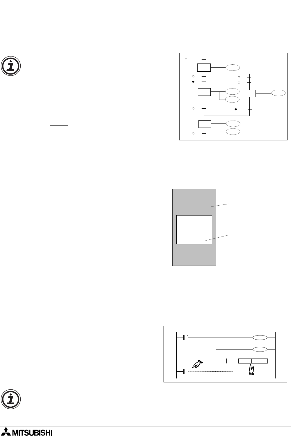
Combined SFC Ladder representation
Sometimes STL programs will be written in hard copy as a combination of both flow diagram
and internal sub-program. (example shown below).
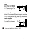
Identification of contact states
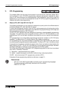
3.3 How To Start And End An STL Program
Before any complex programming can be undertaken the basics of how to start and more
importantly how to finish an STL program need to be examined.
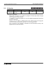
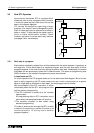
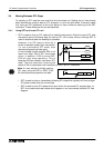
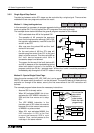
3.3.1 Embedded STL programs
An STL style program does not have to
entirely replace a standard ladder logic
program. In fact it might be very difficult to do
so. Instead small or even large section of STL
program can be entered at any point in a
program. Once the STL task has been
completed the program must go back to
processing standard program instructions until
the next STL program block. Therefore,
identifying the start and end of an STL
program is very important.
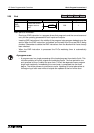
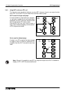
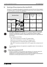
3.3.2 Activating new states
Once an STL step has been selected, how is it used and how is the program ‘driven’?
This is not so difficult, if it is considered that for an STL step to be active its associated state
coil must be ON. Hence, to start an STL sequence all that has to be done is to drive the
relevant state ON.
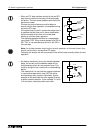
There are many different methods to drive a
state, for example the initial state coils could
be pulsed, SET or just included in an OUT
instruction. However, within Mitsubishi’s STL
programming language an STL coil which is
SET has a different meaning than one that is
included in an OUT instruction.
M8002
X0
X1
S 0
S 26
X0
X1
X15
S 22
S 27
K20
K20
T0
T7
Y22
T0
Y27
T7
Y20
Y26
• Please note the following convention
is used:
Normally Open contact
Normally Closed contact
Common alternatives are ‘a’ and ‘b’
identifiers for Normally Open,
Normally Closed states or often a line
drawn over the top of the Normally
Close
d contact name is used, e.g.
X000.
LD
OUT
LD
SET
STL
OUT
LDI
OUT
RET
LD
OUT
RST
X000
Y004
X002
S009
S009
Y010
X003
Y006
X005
Y007
M080
Normal Ladder Program
Embedded STL Program
STL
S 22
SET S 27
T0
Y22
T0
K20
STL
S 27
Note: For normal STL operation it is recommended that the states are selected using the
SET instruction. To activate an STL step its state coil is SET ON.