


FX Series Programmable Controllers Devices in Detail 4
4-38
Assigning grouped bit devices:
As already explained, bit devices can be grouped into 4 bit units. The “n” in KnM0 defines the
number of groups of 4 bits to be combined for data operation. K1 to K4 are allowed for 16bit
data operations but K1 to K8 are valid for 32bit operations.
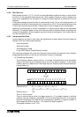
K2M0, for example identifies 2 groups of 4 bits; M0 to M3 and M4 to M7, giving a total of 8 bit
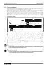
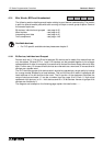
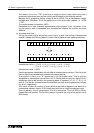
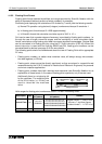
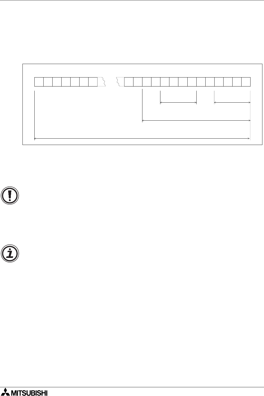
devices or 1 byte. The diagram below identifies more examples of Kn✰ use.
K1X0 : X0 to X3 ➯ 4 bit devices with a head address of X0
K1X6 : X6 to X11 ➯ 4 bit devices with a head address of X6
K3X0 : X0 to X13 ➯ 12 bit devices with a head address of X0
K8X0 : X0 to X37 ➯ 32 bit devices with a head address of X0
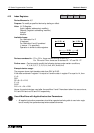
Moving grouped bit devices:
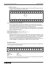
• If a data move involves taking source data and moving it into a destination which is
smaller than the original source, then the overflowing source data is ignored. For
example;
If K3M20 is moved to K1M0 then only M20 to M23 or K1M20 is actually moved. The
remaining data K2M24 or M24 to M31 is ignored.
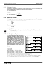
Assigning I/O:
• Any value taken from the available range of devices can be used for the head address
‘marker’ of a bit device group. However, it is recommended to use a 0 (zero) in the
lowest digit place of X and Y devices (X0, X10, X20.....etc). For M and S devices, use of
a multiple of “8” is the most device efficient. However, because the use of such numbers
may lead to confusion in assigning device numbers, it recommended to use a multiple of
“10”. This will allow good correlation to X and Y devices.
1 011 010010110010 00 0 1 0
X0X1X2X3X4X5X6X7X10X11X12X13X14X15X16X31X32X33X34X35X36 X30X37
K1X0K1X6
K3X0
K8X0