


FX Series Programmable Controllers Basic Program Instructions 2
2-6
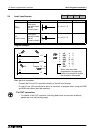
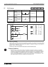
2.6 And, And Inverse
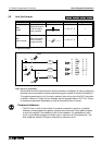
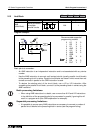
Program example:
Basic points to remember:
- Use the AND and ANI instructions for serial connection of contacts. As many contacts as
required can be connected in series (see following point headed “Peripheral limitations”).
- The output processing to a coil, through a contact, after writing the initial OUT instruction
is called a “follow-on” output (for an example see the program above; OUT Y4). Follow-
on outputs are permitted repeatedly as long as the output order is correct.
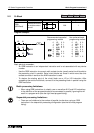
Mnemonic Function Format Devices Program steps
AND
(AND)
Serial connection
of NO (normally
open) contacts
X, Y, M, S, T, C 1
ANI
(AND Inverse)
Serial connection
of NC (normally
closed) contacts
X, Y, M, S, T, C 1
X
X
Y
Y
X
M
T
Y
X2
Y3
AND
X0
X3
T1
ANI
AND
2
0
3
3
3
101
1
4
LD
AND
OUT
LD
ANI
OUT
OUT
AND
0
1
2
3
4
6
7
5
Y3
M101
Y4
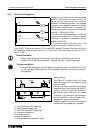
Peripheral limitations:
• The PLC has no limit to the number of contacts connected in series or in parallel.
However, some programming panels, screens and printers will not be able to display
or print the program if it exceeds the limit of the hardware. It is preferable for each
line or rung of ladder program to contain up to a maximum of 10 contacts and 1 coil.
Also, keep the number of follow-on outputs to a maximum of 24.