FX Series Programmable Controllers STL Programming 3
3-16
3.11 Programming Examples
3.11.1 A Simple STL Flow
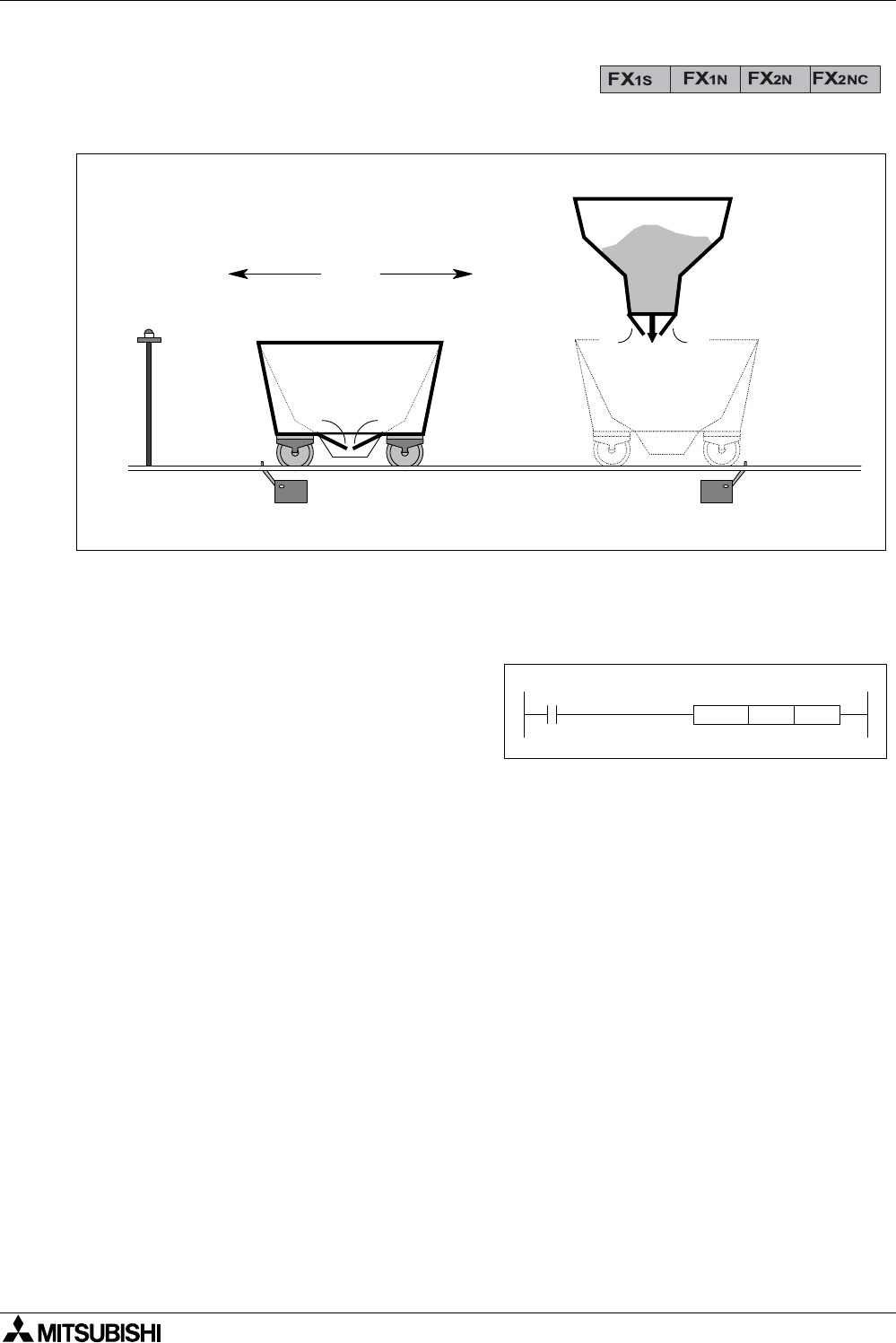
This simple example is an excerpt from a semi-automatic loading-unloading ore truck program.
This example program has a built in, initialization routine which occurs only when the PLC is
powered from OFF to ON. This is achieved by using the special auxiliary relay M8002.
This activates a Zone ReSeT (ZRST is applied
instruction 40) instruction which ensures all of
the operational STL states within the program
are reset. The program example opposite
shows an M8002/ZRST example.
The push button X0 acts as a start button and a mode selection button. The STL state S0 is
initialized with the ZRST instruction. The system waits until inputs X0 and X2 are given and Y
13 is not active. In the scenario this means the ore truck is positioned at the ore discharge
point, i.e. above the position sensor X2. The ore truck is not currently discharging its load, i.e.
the signal to open the trucks unloading doors (Y13) is not active and the start button (X0) has
been given. Once all of the points have been met the program steps on to state S21.
On this state the ore cart is moved (Y10) and positioned (X1) at the loading hopper. If the start
button (X0) is pressed during this stage the ore cart will be set into a repeat mode (M2 is reset)
where the ore truck is immediately returned to the loading hopper after discharging its current
load. This repeat mode must be selected on every return to the loading station.
Once at the loading point the program steps onto state S22. This state opens the hoppers
doors (Y11) and fills the truck with ore. After a timed duration, state S23 is activated and the
truck returns (Y12) to the discharge point (X2).
Y13
X0
Y10
Y12
X2 X1
Y11
Loading hopper
Ore truck
Ore dischange point
Start button
M8002
ZRST S21 S25


