


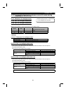
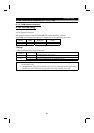

PARAMETERS
102
Pr. 79 "operation mode selection"
Pr. 190 to Pr. 195
(multi-function outputs)
Related parameters
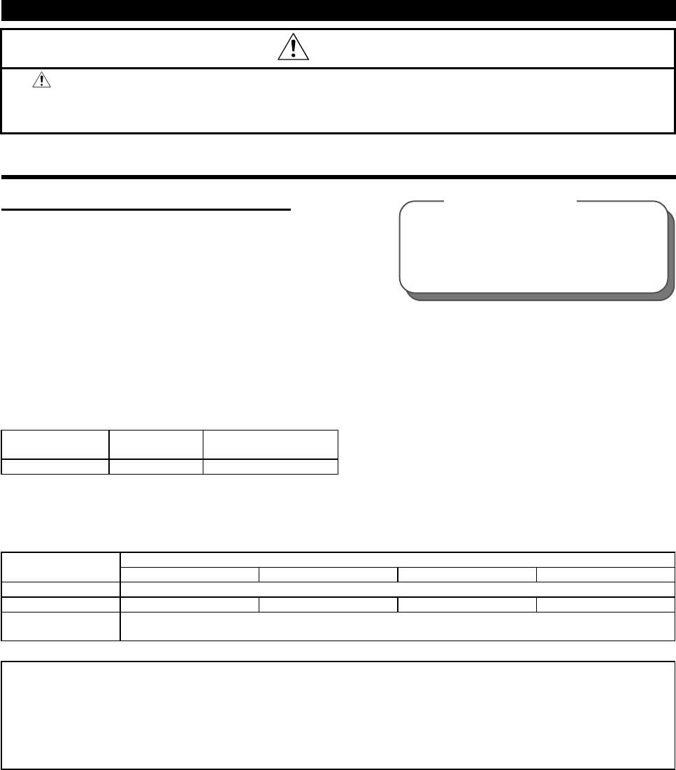
CAUTION
Do not reset the inverter with the start signal on.
Otherwise, the motor will start instantly after resetting, which may lead to hazardous
conditions.
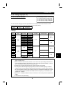
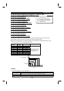
4.2.34 Alarm code output selection (Pr. 76)
Pr. 76 "alarm code output selection"
When an alarm occurs, its code can be output as a 4-bit digital signal from the open collector output
terminals. When programmed operation has been selected, this parameter also serves to output a group
operation signal.
The alarm code can read by a programmable controller etc to show its remedy on a display. Also you can
look at the progress of programmed operation.
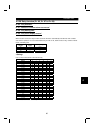
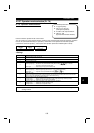
Parameter
Number
Factory
Setting
Setting Range
76 0 0, 1, 2
<Setting>
•
Alarm code output
Output Terminals
Pr. 76 Setting
SU IPF OL FU
0 Alarm code is not output. (Depends on Pr. 190 to Pr. 195).
1 Alarm code bit 3 Alarm code bit 2 Alarm code bit 1 Alarm code bit 0
2
When an alarm occurs, an alarm code signal is output. (Output signal is the same as in 1.)
When operation is normal, an operation status signal is output. (Output signal is the same as in 0.)
Note: 1. For alarm code definitions, refer to page 173.
2. The Pr. 76 setting overrides the Pr. 190 to Pr. 195 settings. Therefore, if you assign other signals
to output terminals SU, IPF, OL and FU using Pr. 190 to Pr. 195, these terminals provide the
output signals as listed above when any of "1 to 2" is set in Pr. 76. This should be noted when
using the functions which use the output signals to exercise control.