


INSTALLATION AND WIRING
21
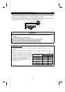
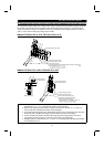
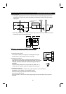
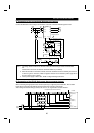
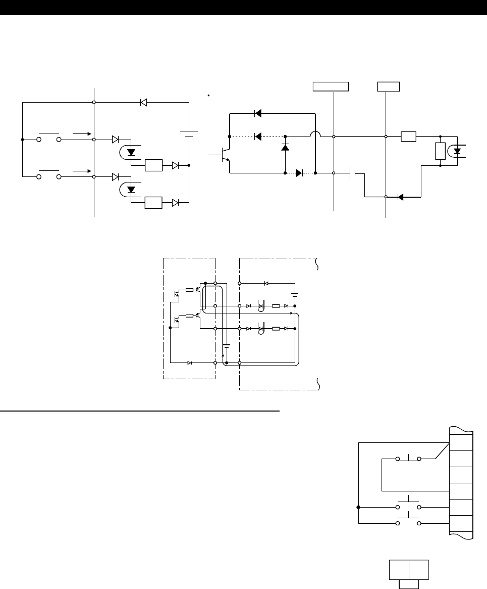
5) Source logic type
•
In this logic, a signal switches on when a current flows into the corresponding signal input terminal.
Terminal PC is common to the contact input signals. Terminal SE is common to the open collector
output signals.
PC
STF
STR
R
R
Current
Current flow related to
RUN signal
24VDC
RUN
SE
1
Inverter
AX80
R
R
9
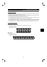
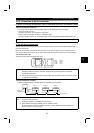
•
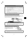
When using an external power supply for transistor output, use terminal SD as a common to prevent
misoperation caused by undesirable current.
AY-80
9
1
2
10
PC
STF
STR
SD
DC24
V
(SD)
DC24V
Inverter
(
4
)
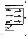
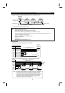
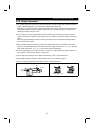
How to use terminals "STOP", "CS" and "PC"
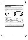
1) Using the "STOP" terminal
A connection example (for sink logic) for self-holding the start signal
(forward rotation, reverse rotation) is shown on the right.
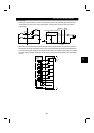
2) Using the "CS" terminal
This terminal is used to perform automatic restart after instantaneous
power failure and commercial power supply-inverter switch-over operation.
<Example: Automatic restart after instantaneous power failure in
sink logic>
Connect terminals CS-SD and set a value other than "9999" in Pr. 57
"coasting time for automatic restart after instantaneous power failure".
MRS
RES
SD
STF
STR
STOP
Reverse
rotation
Stop
Forward
rotation
CS SD
(Short)
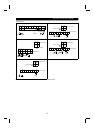
3) Using the "PC" terminal
This terminal can be used as 24VDC-power output using SD as a common terminal.
Specifications: 18V to 26VDC, 0.1A permissible currents
Note that the wiring length should be within 30m (98.43feet).
Do not short terminals PC-SD.
When terminal PC is used as a 24V power supply, leakage current from transistor output cannot be
prevented.