


INSTALLATION AND WIRING
40
(
5
)
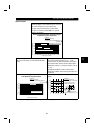
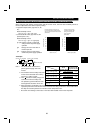
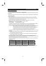
Motor overload protection
When using the electronic overcurrent protection function as motor overload protection, set the rated motor
current in Pr.9 "electronic thermal O/L relay".
When connecting two or more motors to the inverter, install external thermal relays for individual motors.
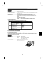
Reference: Motor overload protection characteristics
0 50 100 150 180200
240
180
120
60
Operation time (s)
50% setting
(Note 1, 2)
100% setting
(Note 2)
(Note 1) When you set the 50% value (current
value) of the rated inverter output current.
(Note 2) The % value denotes the percentage of
the current value to the rated inverter
output current, not to the rated motor current.
(Note 3) This characteristic curve will be described
even under operation of 6Hz or higher
when you set the electronic overcurrent
protection dedicated to the Mitsubishi
constant-torque motor.
30Hz or higher
(Note 3)
Inverter output current (%)
(% to rated inverter output current)
Electronic overcurrent
protection for transistor
protection
20Hz
10Hz
Protection activating range
Range on the right of characteristic curve
Normal operating range
Range on the left of characteristic curve
2.3.8 Instructions for compliance with the European standards
(Only the FR-F540-0.75K to 55K units comply. We are now preparing to apply for for compliance with the
other capacity models. The products conforming to the Low Voltage Directive carry the CE mark.)
(1) EMC Directive
1) Our view of transistorized inverters for the EMC Directive
A transistorized inverter is a component designed for installation in a control box and for use with the other
equipment to control the equipment/device. Therefore, we understand that the EMC Directive does not
apply directly to transistorized inverters. For this reason, we do not place the CE mark on the transistorized
inverters. (The CE mark is placed on inverters in accordance with the Low Voltage Directive.) The
European power drive manufacturers' organization (CEMEP) also holds this point of view.
2) Compliance
We understand that the transistorized inverters are not covered directly by the EMC Directive, but the
machines/equipment into which they have been incorporated are covered by the EMC Directive and must
carry the CE marks. Hence, we prepared the technical information "EMC Installation Guidelines"
(information number BCN-A21041-202) so that machines and equipment incorporating transistorized
inverters may conform to the EMC Directive more easily.
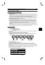
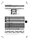
3) Outline of installation method
Install an inverter using the following methods:
* Use the inverter with a European Standard-compliant noise filter.
* For wiring between the inverter and motor, use shielded cables or run them in a metal piping and ground
the cables on the inverter and motor sides with the shortest possible distance.
* Insert a line noise filter and ferrite core into the power and control lines as required.
Full information including the European Standard-compliant noise filter specifications are written in the
technical information "EMC Installation Guidelines" (information number BCN-A21041-202). Please
contact your sales representative.
2