


INSTALLATION AND WIRING
18
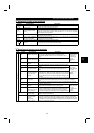
2.2.3 Wiring of the control circuit
(
1
)
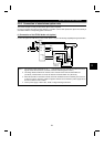
Wiring instructions
1) Terminals SD, SE and 5 are common to the I/O signals and isolated from each other. These common
terminals must not be connected to each other or earthed.
2) Use shielded or twisted cables for connection to the control circuit terminals and run them away from the
main and power circuits (including the 200V relay sequence circuit).
3) The frequency-input signals to the control circuit are micro currents. When contacts are required, use two
or more parallel micro signal contacts or a twin contact to prevent a contact fault.
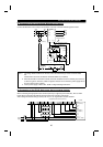
4) It is recommended to use the cables of 0.75mm
2
gauge for connection to the control circuit terminals.
If the cable gauge used is 1.25mm
2
or more, the front cover may be lifted when there are many cables
running or the cables are run improperly, resulting in an operation panel or parameter unit contact fault.
(
2
)
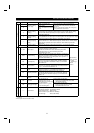
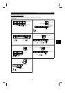
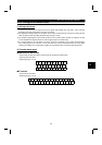
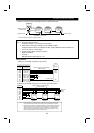
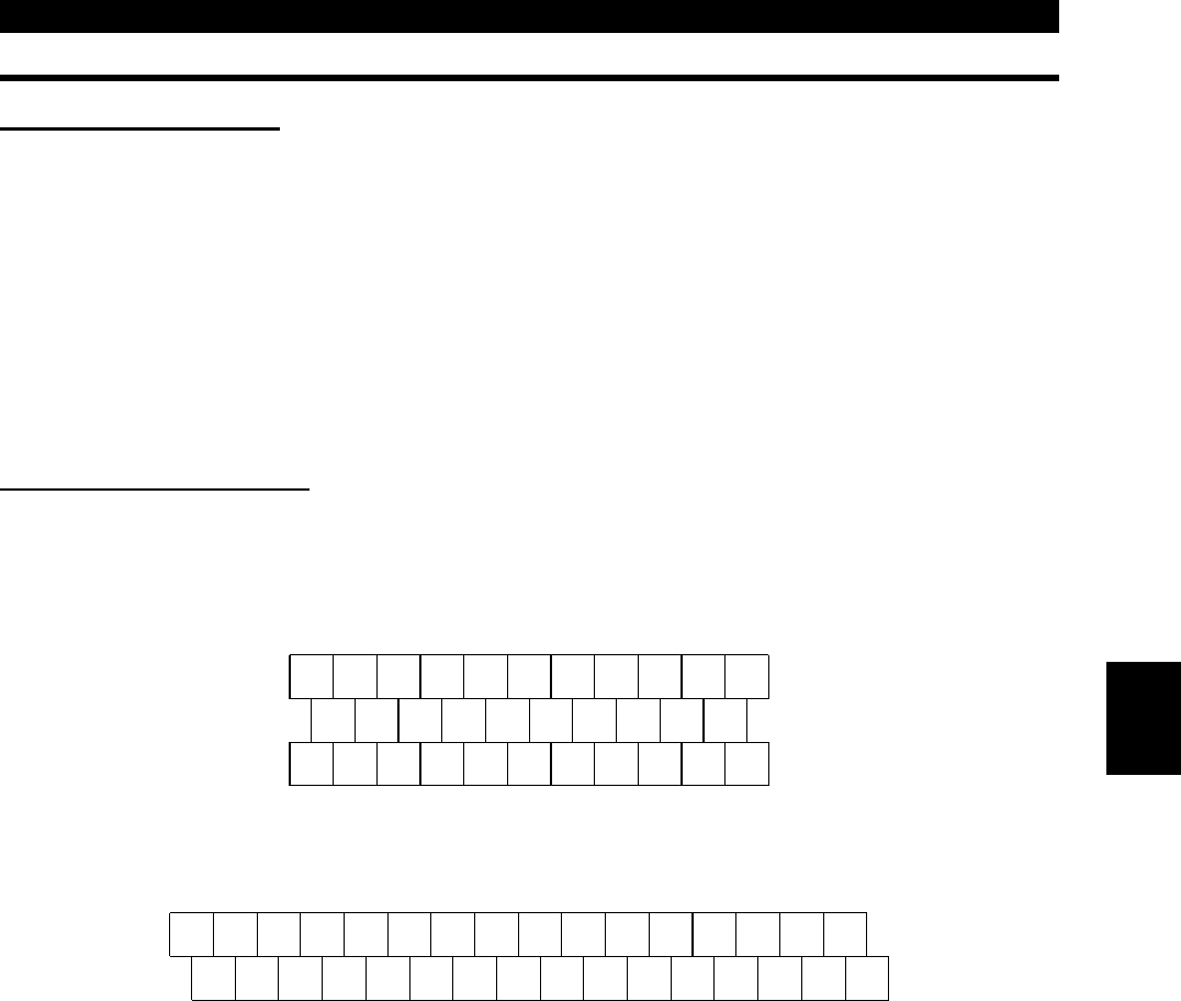
Terminal block layout
•
••
•Japanese and NA version
In the control circuit of the inverter, the terminals are arranged as shown below:
Terminal screw size: M3.5
Tightening torque: 1.2 N
⋅
m
A
RL
SE RUN SU IPF OL FU SD STF STR JOG CS
RM RH RT AU STOP MRS RES SD FM
B C PC AM 10E 10 2 5 4 1
•
••
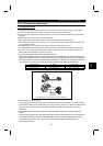
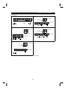
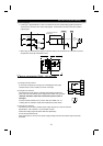
•EC version
Terminal screw size: M3.5
Tightening torque: 1.2 N
⋅
m
A
SE RUN SU LPF OL STOP MRS RES PC STF
B C SD AM 10E 10 2 5 4 1
RL RM RH RT AU
STR JOG CS FM SDFU
2