


APPENDICES
198
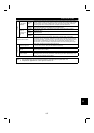
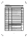
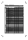
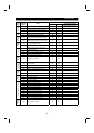
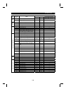
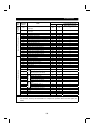
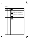
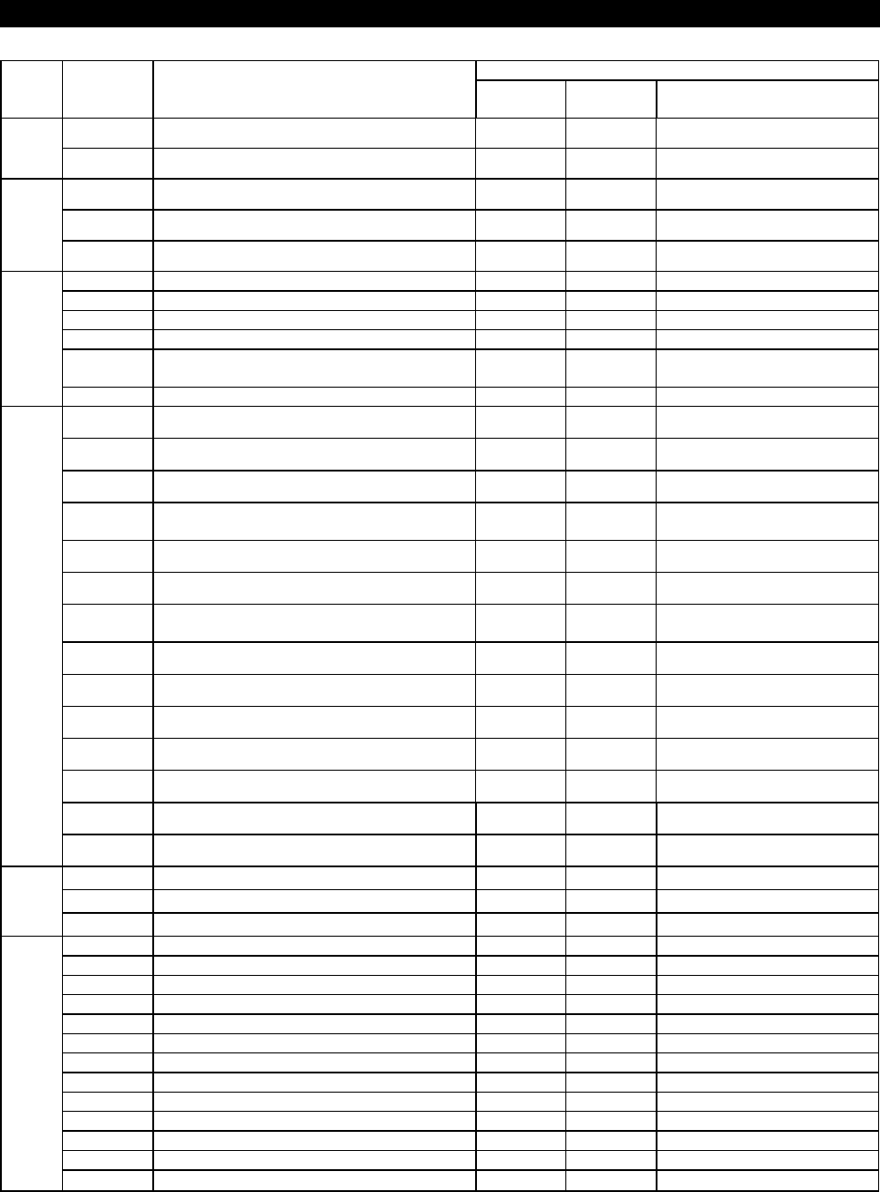
Data Codes
Func-
tion
Parameter
Number
Name
Read Write
Link Parameter Extension
Setting (Data code 7F/FF)
240 Soft-PWM setting 30 B0 2
Sub
function
244 Cooling fan operation selection 34 B4 2
251 Output phase failure protection selection 3B BB 2
252 Override bias 3C BC 2
Additional
function
253 Override gain 3D BD 2
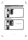
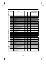
300 BCD code input bias 00 80 3
301 BCD code input gain 01 81 3
302 Binary input bias 02 82 3
303 Binary input gain 03 83 3
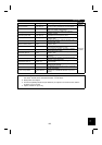
304
Selection of whether digital input and analog
compensation input are enabled or disabled
04 84 3
12-bit digital input
305 Data read timing signal on/off selection 05 85 3
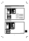
306 Analog output signal selection 06 86 3
307 Setting for zero analog output 07 87 3
308 Setting for maximum analog output 08 88 3
309
Analog output signal voltage/current switch-
over
09 89 3
310 Analog meter voltage output selection 0A 8A 3
311 Setting for zero analog meter voltage output 0B 8B 3
312
Setting for maximum analog meter voltage
output
0C 8C 3
313 Y0 output selection 0D 8D 3
314 Y1 output selection 0E 8E 3
315 Y2 output selection 0F 8F 3
316 Y3 output selection 10 90 3
317 Y4 output selection 11 91 3
318 Y5 output selection 12 92 3
Analog output, digital output
319 Y6 output selection 13 93 3
320 RA1 output selection 14 94 3
321 RA2 output selection 15 95 3
Relay
output
322 RA3 output selection 16 96 3
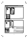
330 RA output selection 1E 9E 3
331 Inverter station number 1F 9F 3
332 Communication speed 20 A0 3
333 Stop bit length 21 A1 3
334 Parity check yes/no 22 A2 3
335 Communication retry count 23 A3 3
336 Communication check time interval 24 A4 3
337 Waiting time setting 25 A5 3
338 Operation command write 26 A6 3
339 Speed command write 27 A7 3
340 Link start mode selection 28 A8 3
341 CR
•
LF yes/no selection 29 A9 3
Computer link function
342
E
2
PROM write yes/no
2A AA 3