


INSTALLATION AND WIRING
26
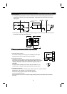
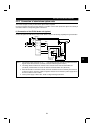
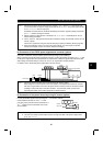
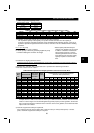
Note: 1. Remove the jumpers across terminals R-R1 and S-S1 <L
1
-L
11
and L
2
-L
21
> of the inverter and
connect the control circuit power supply to terminals R1-S1 <L
11
-L
21
>. The power input terminals
R, S, T < L
1
, L
2
, L
3
> must be kept open.
Accidental connection to these terminals will damage the inverter. Opposite polarity of terminals
N, P <
−
,
+
> will also damage the inverter.
2. Always match the voltage phases of terminals R, S, T < L
1
, L
2
, L
3
> and terminals R4, S4, T4
before making connection.
3. Use Pr. 180 to Pr. 186 (input terminal function selection) to assign the terminals used for the X10
and X11 signals.
Use the X11 signal when using the computer link plug-in option (FR-A5NR). (Refer to page 80)
4. When connecting the FR-HC, use sink logic (factory setting). For source logic, the FR-HC
cannot be connected. (For the EC version, select the sink logic.)
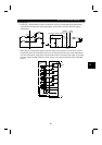
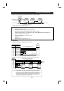
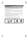
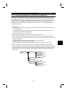
(4) Connection of the FR-RC power regeneration converter (option)
(For power coordination, always install the power factor-improving reactor (FR-BAL).)
When connecting the FR-RC power regeneration converter, connect the inverter terminals (P, N <
+
,
−
>) and
FR-RC power regeneration converter terminals as shown below so that their signals match with each other.
After making sure that the wiring is correct, set "0" in Pr. 30 "regenerative function selection".
For details, refer to the FR-RC power regeneration converter manual.
NFB FR-BAL
R/L
1
S/L
2
T/L
3
P/
+
N/
−
converter
Power supply
Inverter
R
〈
L
1
〉
S
〈
L
2
〉
T
〈
L
3
〉
N
〈−〉
P
〈+〉
FR-RC power regeneration
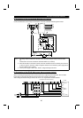
Note: 1. How to connect the FR-BAL power factor improving AC reactor (option)
When using two or more inverters in the same system, small impedance between the inverters
will cause a regenerative current from the power return converter to leak into the other inverters,
resulting in overcurrent alarm of the other inverters. To prevent this, install a power factor
improving AC reactor on the power supply side for all the inverters.
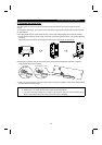
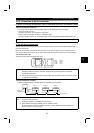
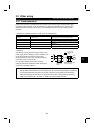
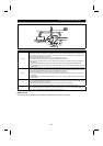
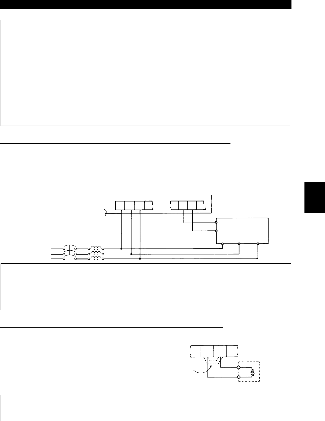
(5) Connection of the power factor improving DC reactor (option)
Connect the FR-BEL power factor improving DC
reactor between terminals P1-P
〈
P1-
+〉
. In this
case, the jumper connected across terminals P1-P
〈
P1-
+〉
must be removed. Otherwise, the reactor
will not function.
<Connection method>
P1
FR-BEL
Remove
the jumper.
P
〈+〉
Note: 1. The wiring distance should be within 5m (16.40feet).
2. The size of the cables used should be equal to or larger than that of the power supply cables
(R, S, T)
〈
L
1
, L
2
, L
3
〉
.
2