


PARAMETERS
148
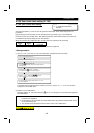
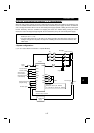
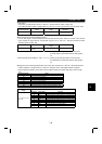
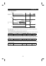
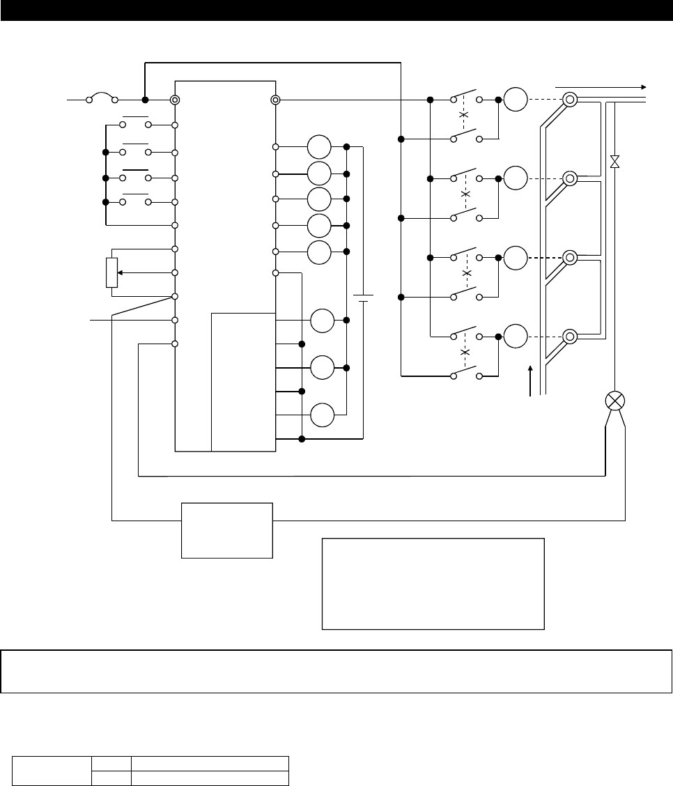
(2) Pr. 501 "motor switch-over selection" = 1 (Alternative Method), 2 (Direct Method)
RST UVW
JOG
SD
10
2
5
1
4
FU
OL
IPF
SE
RI01
R01
RI02
MC
RI01
DC24V
SU
RUN
R03
RI04
R04
R02
RI03
1A
1C
2A
2C
3A
3C
R01
MC (Note 2)
STF
STR
FR-A5AR
RI01
R02
RI02
R03
RI03
R04
RI04
RT
X14
X24
Inverter
Power
supply
R01
RI02
R02
RI03
MC
R03
RI04
R04
M1
M2
M3
M4
Setting
potentiometer
(Set point setting)
Deviation signal
Supplied water
Detector
(Process value) 4 to 20mA
Distributed water
Example
PUMP4
PUMP3
PUMP2
PUMP1
Reverse rotation
Forward rotation
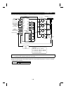
Advanced PID
control selection
For 2-wire
type
(Option)
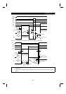
(Note 1)
Sink logic
When Pr. 183=14, Pr. 185=24
Pr. 194=45, Pr. 193=41, Pr. 192=46
Pr. 191=42, Pr. 190=47, Pr. 320=43
Pr. 321=48, Pr. 322=44
Power
supply
024V
-+
action switching
PID forward
-reverse
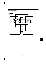
Note: 1. When driving three or more motors, use the inboard option (FR-A5AR).
2. Always provide mechanical interlocks for the MCs.
#
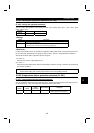
Assign the advanced PID control selection signal X14 to any terminal using any of Pr. 180 to Pr. 186 (input
terminal function selection).
ON Advanced PID control valid
X14 signal
OFF Advanced PID control invalid