


INSTALLATION AND WIRING
25
(
2
)
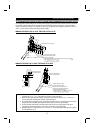
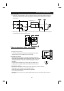
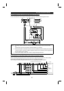
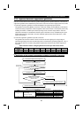
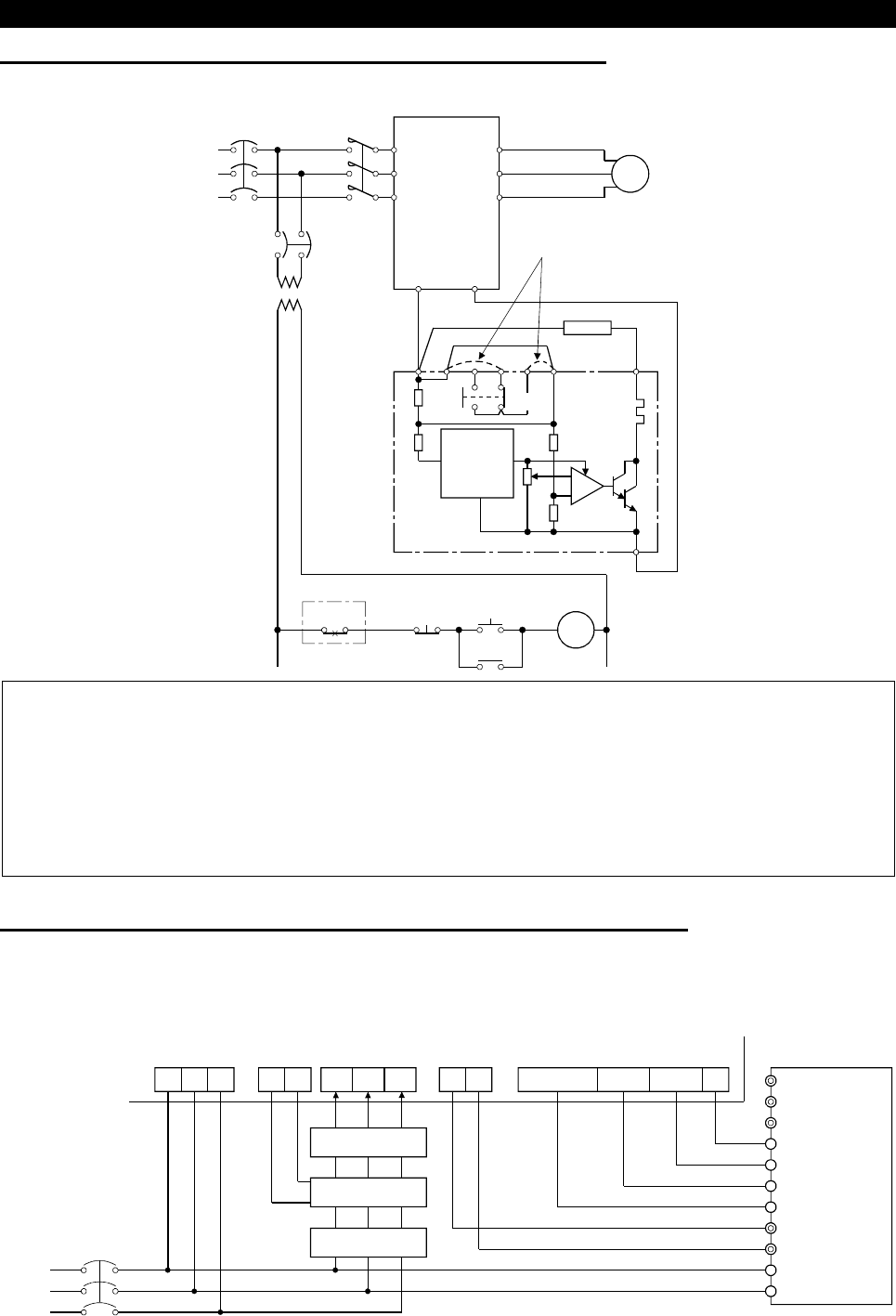
Connection of the conventional BU brake unit (option)
Connect the BU brake unit correctly as shown below. Incorrect connection will damage the inverter.
MC
R
〈
L
1
〉
S
〈
L
2
〉
T
〈
L
3
〉
U
V
W
IM
Inverter
HCHBHA TB
HC HB
ON
MC
MC
OFF
P
〈
+
〉
N
〈
–
〉
P
OCR
PR
OCR
N
NFB
PC
Brake unit
Remove jumpers.
Discharge resistor
Constant-
voltage
power
supply
BU brake unit
Comparator
Motor
T (Note 3)
+
-
Note: 1. The wiring distance between the inverter, brake unit and discharge resistor should be within
2m.
If twisted wires are used, the distance should be within 5m (16.40feet).
2. When the transistor in the brake unit fails, the brake transistor bacomes extremely hot and it has
a chance to get fire. Therefore, install a magnetic contactor on the inverter's power supply side to
shut off current in case of failure.
3. For the power supply of 400V class, install a voltage-reducing transformer.
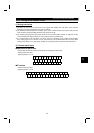
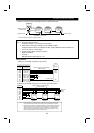
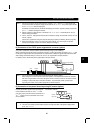
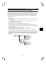
(3) Connection of the FR-HC high power factor converter (option)
When connecting the high power factor converter (FR-HC) to suppress power harmonics, wire as shown
below. Wrong connection will damage the high power factor converter and inverter.
After making sure that the wiring is correct, set "2" in Pr. 30 "regenerative function selection".
X10 (Note 3)
X11 (Note 3)
N
〈
–
〉
P
〈
+
〉
R1
〈
L
11
〉
S1
〈
L
21
〉
RES
SD
T
〈
L
3
〉
S
〈
L
2
〉
(Note 1)
R
〈
L
1
〉
NFB
R S T N P Y1 or Y2 RDY RSO SE
Inverter
(Note 1)
High power factor converter (FR-HC)
Power
supply
R4 S4 T4
From FR-HCL02
MC1 MC2
External box
MC1
MC2
FR-HCL01
R4 S4 T4
R3 S3 T3
R2 S2 T2
RST