


PROTECTIVE FUNCTIONS
183
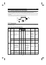
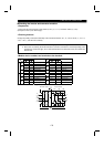
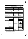
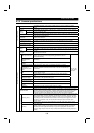
Measuring Points and Instruments
Item Measuring Point Measuring Instrument
Remarks
(Reference Measured Value) *
Power supply voltage V
1
Across R-S, S-T and T-R
〈
Across L
1
-L
2
, L
2
-L
3
and L
3
-L
1
〉
Moving-iron type AC voltmeter
Commercial power supply
Within permissible AC voltage
fluctuation (Refer to 184 page)
Power supply side
current I
1
R, S and T line currents
〈
L
1
, L
2
and L
3
line currents
〉
Moving-iron type AC ammeter
Power supply side power
P
1
At R, S and T, and across R-S,
S-T and T-R
〈
At L
1
, L
2
and L
3
, and across
L
1
-L
2
, L
2
-L
3
and L
3
-L
1
〉
Electrodynamic type single-
phase wattmeter
P1 = W
11
+
W
12
+
W
13
(3-wattmeter method)
Power supply side power
factor Pf
1
Calculate after measuring power supply voltage, power supply side current and power supply side power.
×
100%
3 V
1
×
I
1
P
1
Pf
1
=
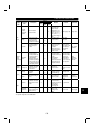
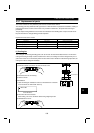
Output side voltage V
2
Across U-V, V-Wand W-U
Rectifier type AC voltmeter
(Note 1) (Not moving-iron type)
Difference between phases is
within
±
1% of maximum output
voltage.
Output side current I
2
U, V and W line currents
Moving-iron type AC ammeter
(Note 3)
Current should be equal to or less
than rated inverter current.
Difference between phases is 10%
or lower.
Output side power P
2
At U, V and W, and across U-V
and V-W
Electrodynamic type single-
phase wattmeter
P
2
= W
21
+
W
22
2-wattmeter method
(or 3-wattmeter method)
Output side power factor
Pf
2
Calculate in similar manner to power supply side power factor.
×
100%
3 V
2
×
I
2
P
2
Pf
2
=
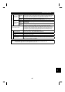
Converter output Across P-N
〈
Across
+
and
−〉
Moving-coil type (such as
tester)
POWER lamp lit
1.35
×
V
1
Maximum 380V (760V) during
regenerative operation
Across 2 (
+
) –5 0 to 5V/0 to 10VDC
Across 1 (
+
) –5 0 to
±
5V/0 to
±
10VDCFrequency setting signal
Across 4 (
+
) –5 4 to 20mADC
Across 10 (
+
) –5 5VDC
Frequency setting power
supply
Across 10E (
+
) –5 10VDC
“5” is
common.
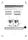
Across FM (
+
) –SD
Approximately 5VDC at
maximum frequency
(without frequency meter)
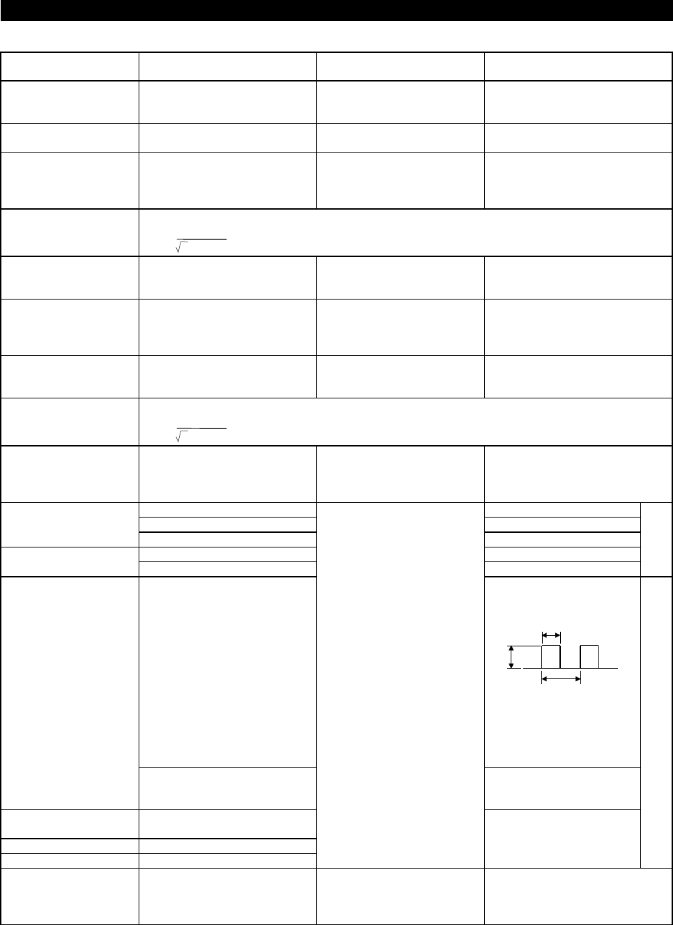
DC8V
T1
T2
Pulse width T1:
Adjusted by Pr.900
Pulse cycle T2: Set by Pr.55
(Valid for frequency
monitoring only)
Frequency meter signal
Across AM (
+
) –5
Approximately 10DVC at
maximum frequency
(without frequency meter)
Start signal
Select signal
Across STF, STR, RH, RM, RL,
JOG, RT, AU, STOP, CS (
+
) -SD
Reset Across RES (
+
) –SD
Output stop Across MRS (
+
) –SD
Moving-coil type (Tester, etc.
may be used) (Internal
resistance: 50k
Ω
or larger)
20 to 30VDC when open.
ON voltage: 1V or less
SD is common.
Alarm signal
Across A-C
Across B-C
Moving-coil type
(such as tester)
Continuity check (Note 2)
<At OFF> <At ON>
Across A-C: Discontinuity Continuity
Across B-C: Continuity Discontinuity
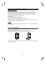
Note 1. Accurate data will not be obtained by a tester.
2. When Pr. 195 "A, B, C terminal function selection" setting is positive logic.
3. When the carrier frequency exceeds 5kHz, do not use the instrument because eddy-current losses occurring in the metallic
parts inside the instrument will increase and may lead to burnout.
In this case, use an approximate effective value type instrument.
* Values in parentheses are those of the 400V class.