


PARAMETERS
155
Pr. 54 "FM terminal function selection"
Pr. 55 "frequency monitoring reference"
Pr. 56 "current monitoring reference"
Pr. 158 "AM terminal function selection"
Related parameters
4.2.55 Meter (frequency meter) calibration (Pr. 900, Pr. 901)
Pr. 900 "FM terminal calibration"
Pr. 901 "AM terminal calibration"
#
By using the operation panel/parameter unit, you can calibrate a meter connected to terminal FM to full
scale.
#
Terminal FM provides the pulse output. By setting Pr. 900, you can calibrate the meter connected to the
inverter from the parameter unit without providing a calibration resistor.
#
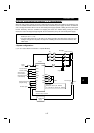
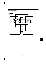
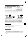
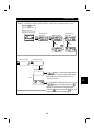
You can display a digital value on a digital counter using the pulse train signal from terminal FM. A 1440
pulses/s output is provided at the full scale value as explained in the section of Pr. 54. When the running
frequency has been selected for monitoring, the ratio of this FM terminal output frequency can be set in
Pr. 55.
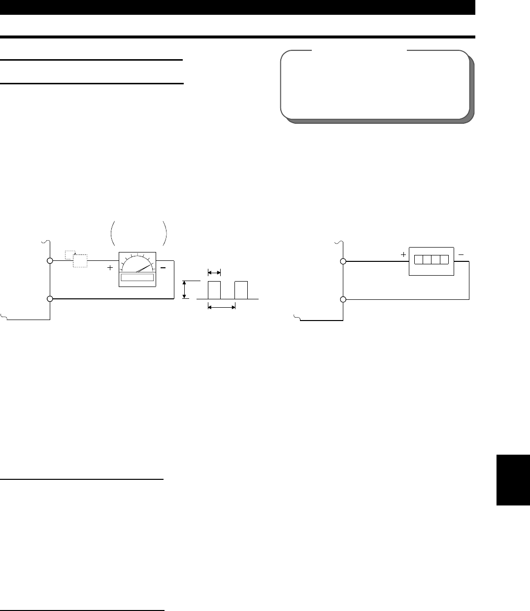
1440 pulses/s
(AM) FM
(5) SD
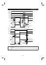
Note: The parameter is factory-set to 1mA full-scale or
1440 pulses/s FM output frequency at 60Hz.
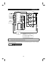
(Digital meter)
8VDC
T2
T1
1mA
(AM) FM
(5) SD
Meter
1mA full scale
Analog meter
Pulse width T1
Pulse period T2
:Adjusted with Pr. 900
:Set in Pr. 55 (frequency monitoring)
Set in Pr. 56 (current monitoring)
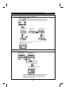
*
( )
( )
Calibration
resistor
( )
( )
* Not needed when the operation panel (FR-DU04) or parameter unit (FR-PU04) is used for calibration.
Used when calibration must be made near the frequency meter for such a reason as a remote frequency
meter. However, the frequency meter needle may not deflect to full-scale if the calibration resistor is
connected.
In this case, use this resistor and the operation panel or parameter unit together to make calibration.
#
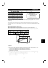
Terminal AM is factory-set to provide a 10VDC output in the full-scale state of each monitored data. Pr. 901
allows the output voltage ratio (gain) to be adjusted according to the meter reading. Note that the maximum
output voltage is 10VDC.
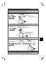
(1) Calibration of terminal FM
1) Connect a meter (frequency meter) across inverter terminals FM-SD. (Note the polarity. FM is the
positive terminal.)
2) When a calibration resistor has already been connected, adjust the resistance to "0" or remove the
resistor.
3) Set any of "1 to 3, 5, 6, 8, 10 to 14, 17 and 21" in Pr. 54.
When the running frequency or inverter output current has been selected as the output signal, preset in
Pr. 55 or Pr. 56 the running frequency or current at which the output signal is 1440 pulses/s.
At this 1440 pulses/s, the meter normally deflects to full scale.
(2) Calibration of terminal AM
1) Connect a 0-10VDC meter (frequency meter) across inverter terminals AM-5. (Note the polarity. AM is
the positive terminal.)
2) Set any of "1 to 3, 5, 6, 8, 10 to 14, 17 and 21" in Pr. 158.
When the running frequency or inverter output current has been selected as the output signal, preset in
Pr. 55 or Pr. 56 the running frequency or current at which the output signal is 10V.
3) When outputting a signal which cannot achieve a 100% value easily by operation, e.g. output current,
set "21" in Pr. 158 and perform the following operation. After that, set "2" (output current, for example)
in Pr. 158.
4