


PROTECTIVE FUNCTIONS
173
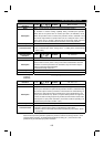
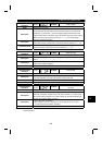
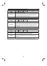
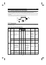
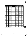
5.1.4 Alarm code output
By setting Pr. 76 "alarm code output selection", an alarm definition can be output as a 4-bit digital signal. This
signal is output from the open collector output terminals equipped as standard on the inverter.
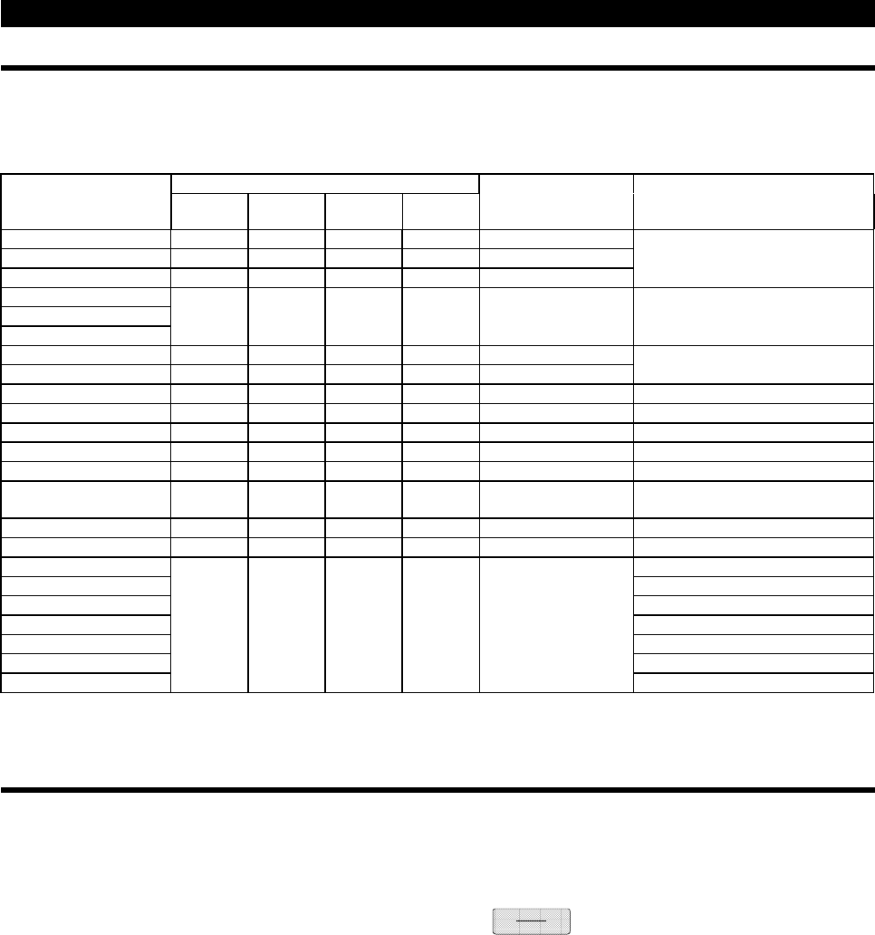
Correlations between alarm definitions and alarm codes are as follows.
Output Terminal Signal On-OffOperation Panel
Display
(FR-DU04)
SU IPF OL FU
Alarm Code Alarm Output (across B-C)
E.OC1 0 0 0 1 1
E.OC2 0 0 1 0 2
E.OC3 0 0 1 1 3
Provided (Open)
E.OV1
E.OV2
E.OV3
0 1 0 0 4 Provided (Open)
E.THM 0 1 0 1 5
E.THT 0 1 1 0 6
Provided (Open)
E.IPF 0 1 1 1 7 Provided (Open)
E.UVT 1 0 0 0 8 Provided (Open)
E.FIN 1 0 0 1 9 Provided (Open)
E. GF 1 0 1 1 B Provided (Open)
E.OHT 1 1 0 0 C Provided (Open)
E.OLT 1 1 0 1 D
Not provided (Closed) (Provided
when OLT is displayed (Open))
E.OPT 1 1 1 0 E Provided (Open)
E.OP1 to E.OP3 1 1 1 0 E Provided (Open)
E. PE Provided (Open)
E.PUE Provided (Open)
E.RET Provided (Open)
E.LF Provided (Open)
E.CPU Provided (Open)
E. 6 Provided (Open)
E. 7
1111 F
Provided (Open)
(Note) 0: Output transistor OFF, 1: Output transistor ON (common terminal SE)
The alarm output assumes that Pr. 195 setting is "99" (factory setting).
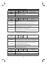
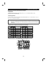
5.1.5 Resetting the inverter
The inverter can be reset by performing any of the following operations. Note that the electronic overcurrent
protection's internal heat calculation value and the number of retries are cleared (erased) by resetting the
inverter.
Operation 1: Using the operation panel (FR-DU04), press the
STOP
RESET
key to reset the inverter.
Operation 2: Switch power off once, then switch it on again.
Operation 3: Switch on the reset signal (RES).