


INSTALLATION AND WIRING
30
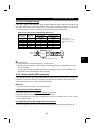
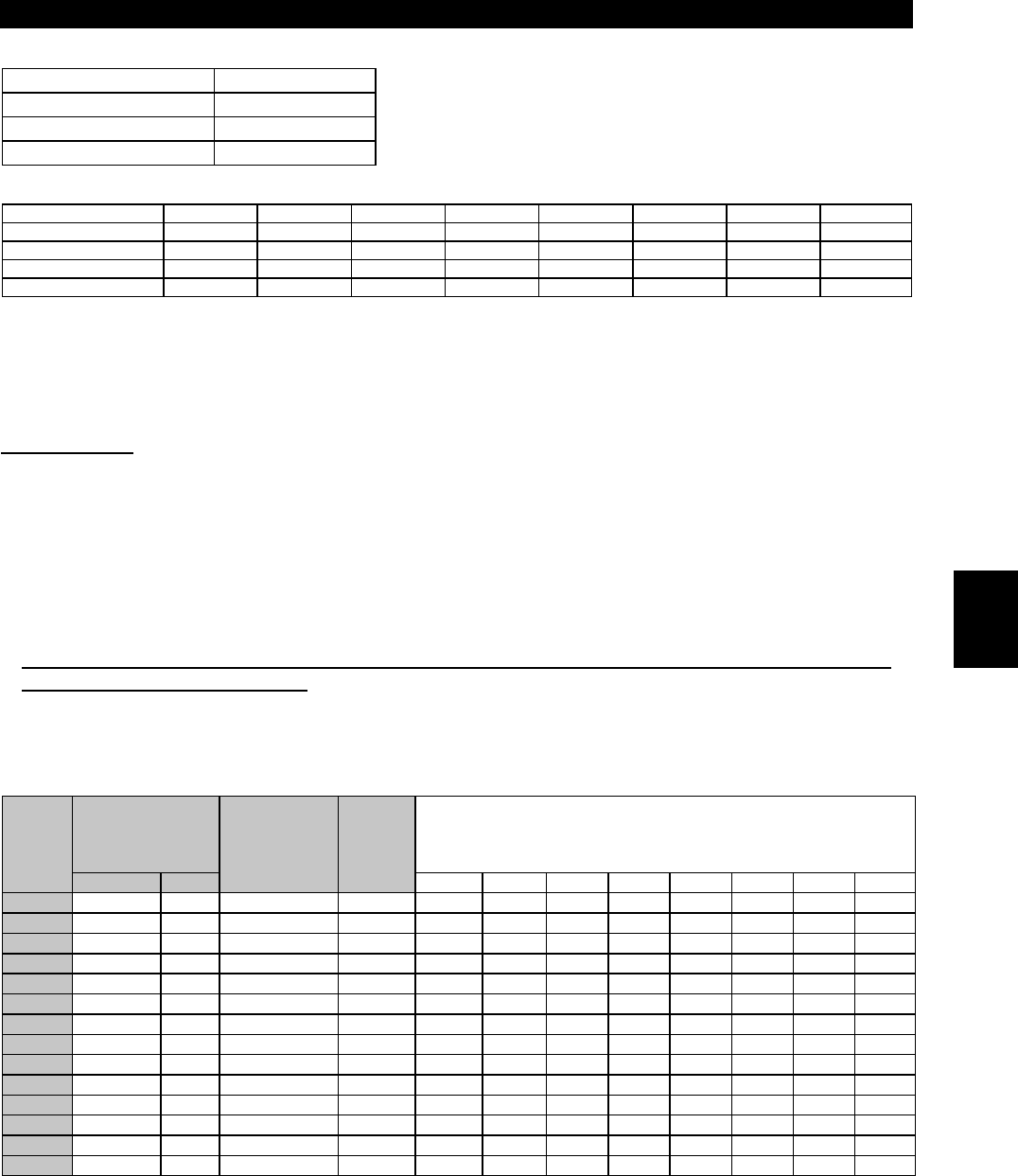
Table 3 Equivalent Capacity Limits
Received Power Voltage Reference Capacity
6.6kV 50kVA
22/33kV 300kVA
66kV or more 2000kVA
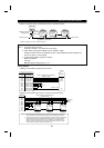
Table 4 Harmonic Content (Values at the fundamental current of 100%)
Reactor 5th 7th 11th 13th 17th 19th 23rd 25th
Not used 65 41 8.5 7.7 4.3 3.1 2.6 1.8
Used (AC side) 38 14.5 7.4 3.4 3.2 1.9 1.7 1.3
Used (DC side) 30 13 8.4 5.0 4.7 3.2 3.0 2.2
Used (AC, DC sides) 28 9.1 7.2 4.1 3.2 2.4 1.6 1.4
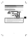
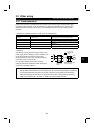
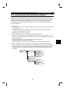
1) Calculation of equivalent capacity (P0) of harmonic generating equipment
The “equivalent capacity” is the capacity of a 6-pulse converter converted from the capacity of
consumer’s harmonic generating equipment and is calculated with the following equation. If the sum of
equivalent capacities is higher than the limit in Table 3, harmonics must be calculated with the following
procedure:
P0 =
Σ
(Ki
×
Pi) [kVA]
Ki: Conversion factor (refer to Table 2)
Pi: Rated capacity of harmonic generating equipment* [kVA]
i: Number indicating the conversion circuit type
* Rated capacity: Determined by the
capacity of the applied motor and found
in Table 5. It should be noted that the
rated capacity used here is used to
calculate generated harmonic amount
and is different from the power supply
capacity required for actual inverter
drive.
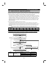
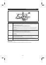
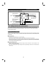
2) Calculation of outgoing harmonic current
Outgoing harmonic current = fundamental wave current (value converted from received power voltage)
×
operation ratio
×
harmonic content
•
Operation ratio: Operation ratio = actual load factor
×
operation time ratio during 30 minutes
•
Harmonic content: Found in Table 4.
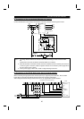
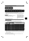
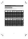
Table 5 Rated Capacities and Outgoing Harmonic Currents for Inverter Drive
Rated Current [A]
Fundamental
Wave Current
Converted
from 6.6kV
Rated
Capacity
Fundamental Wave Current Converted from 6.6kV
(No reactor, 100% operation ratio)
Applied
Motor
(kW)
200V 400V (mA) (kVA) 5th 7th 11th 13th 17th 19th 23rd 25th
0.75 2.74 (Note) 1.37 83 0.97 53.95 34.03 7.055 6.391 3.569 2.573 2.158 1.494
1.5 5.50 (Note) 2.75 167 1.95 108.6 68.47 14.20 12.86 7.181 5.177 4.342 3.006
2.2 7.93 (Note) 3.96 240 2.81 156.0 98.40 20.40 18.48 10.32 7.440 6.240 4.320
3.7 13.0 (Note) 6.50 394 4.61 257.1 161.5 33.49 30.34 16.94 12.21 10.24 7.092
5.5 19.1 9.55 579 6.77 376.1 237.4 49.22 44.58 24.90 17.95 15.05 10.42
7.5 25.6 12.8 776 9.07 504.4 318.2 65.96 59.75 33.37 24.06 20.18 13.97
11 36.9 18.5 1121 13.1 728.7 459.6 95.29 86.32 48.20 34.75 29.15 20.18
15 49.8 24.9 1509 17.6 980.9 618.7 128.3 116.2 64.89 46.78 39.24 27.16
18.5 61.4 30.7 1860 21.8 1209 762.6 158.1 143.2 79.98 57.66 48.36 33.48
22 73.1 36.6 2220 25.9 1443 910.2 188.7 170.9 95.46 68.82 57.72 39.96
30 98.0 49.0 2970 34.7 1931 1218 252.5 228.7 127.7 92.07 77.22 53.46
37 121 60.4 3660 42.8 2379 1501 311.1 281.8 157.4 113.5 95.16 65.88
45 147 73.5 4450 52.1 2893 1825 378.3 342.7 191.4 138.0 115.7 80.10
55 180 89.9 5450 63.7 3543 2235 463.3 419.7 234.4 169.0 141.7 98.10
Note: When a motor of 3.7kW or less capacity is driven by a transistorized inverter of more than 3.7kW. For
example, when a 3.7kW or less motor is driven by a 5.5kW transistorized inverter, the transistorized
inverter is not the target of the household appliances/general-purpose products guideline, but because
they must be included in the calculation of the harmonic current of the guideline, the fundamental wave
input currents are indicated.
3) Harmonic suppression technique requirement
If the outgoing harmonic current is higher than; maximum value per 1kW (contract power)
×
contract
power, a harmonic suppression technique is required.
2