


RT-PRC031-EN 101
Mechanical Specifications
Cooling System
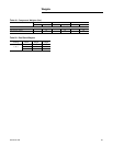
Chilled Water Coil
Coils shall be of type 5W, W, or WD
and have a tube in sheet design with
5/8” OD, 0.020” copper tubing
mechanically bonded to aluminum
fins. Headers shall be constructed of
copper tubing with steel pipe
connections. Coil casing shall be a
minimum 16-gauge G90 galvanized
steel with formed end supports and
top and bottom channels.
Multiple row and fin series options
shall be available including 2, 4, 6, or
8 rows and 80, 108, 144, or 168 fins
per foot. Optional, performance
enhancing, turbulators shall
available for all chilled water coils. All
coils shall be factory burst tested at
300 PSIG and leak tested at 200 PSIG.
All coils shall have drain holes.
Water diverters and a double sloped
galvanized drain pan shall be
provided to direct condensate to both
sides of the unit.
Water Valve
A 1.5”, 2.0”, 2.5”, or 3.0” water
modulating valve with actuator and
linkage shall be provided by the
manufacturer. Valve, actuator, and
linkage shall be field installed and
piped by the piping contractor.
External Piping Enclosure
A piping cabinet shall be supplied by
the manufacturer (factory
assembled) when the chilled water
cooling option is selected. The
piping cabinet shall be mounted
external to the air handler unit and
shipped separate to be field installed.
The piping cabinet shall have a
removable panel.
Air Handling System
Supply Fan
Standard or low airflow supply fan
shall have a single fan assembly with
double width, double inlet, airfoil fan,
motor and fixed pitch sheave drive.
All fans shall be statically and
dynamically balanced for the
operating envelop. It shall be tested
in the factory. Supply fans shall be
test run in unit as part of the unit test.
Fan operating envelop rpm shall be
below first critical speed. Fan shafts
shall be mounted on two grease
lubricated ball bearings designed for
200,000 hours average life. Extended
grease lines shall allow greasing of
bearings from section base rail. Fan
motor and fan assembly shall be
mounted on common base to allow
consistent belt tension with no
relative motion between fan and
motor shafts. Entire assemblies shall
be completely isolated from unit by
two-inch deflection spring isolators.
Controls
Unit shall be completely factory
wired with necessary control and
contactor pressure lugs or terminal
block for power wiring. Units shall
provide an internal location for a
non-fused disconnect with external
handle for safety.
Unit Controller
DDC microprocessor controls shall
be provided to control all unit
functions. The control system shall
be suitable to control CV or VAV
applications. The controls shall be
factory installed and mounted in the
main control panel. All factory
installed controls shall be fully
commissioned (run tested) at the
factory. The unit shall have a Human
Interface Panel with a 16 key keypad,
a 2 line X 40 character clear English
display as standard to provide the
operator with full adjustment and
display of control data functions. The
unit controls shall be used as a stand-
alone controller, or as part of a
building management system
involving multiple units.
1
The unit shall be equipped with a
complete microprocessor control
system. This system shall consist of
temperature and pressure
(thermistor and transducer) sensors,
printed circuit boards (modules), and
a unit mounted Human Interface
Panel. Modules (boards) shall be
individually replaceable for ease of
service. All microprocessors, boards
and sensors shall be factory
mounted, wired and tested.
The microprocessor boards shall be
standalone DDC controls not
dependent on communications with
an on-site PC or a Building
Management Network. The
microprocessors shall be equipped
with onboard diagnostics, indicating
that all hardware, software and
interconnected wiring are in proper
operating condition.
The modules (boards) shall be
protected to prevent RFI and voltage
transients from affecting the board
circuits. All field wiring shall be
terminated at separate, clearly
marked terminal strip. Direct field
wiring to the I/O boards is not
acceptable.
The microprocessor's memory shall
be non-volatile EEPROM type
requiring no battery or capacitive
backup, while maintaining all data.
2
Zone sensors shall be available in
several combinations with selectable
features depending on sensor.
3
The Human Interface Panel keypad
display character format shall be 40
characters x 2 lines. The character
font shall be 5 x 7 dot matrix plus
cursor. The display shall be
Supertwist Liquid Crystal Display
(LCD) with blue characters on a gray/
green background which provides
high visibility and ease of interface.
The display format shall be in clear
English.
4
The keypad shall be equipped with
16 individual touch-sensitive
membrane key switches. The
switches shall be divided into four
separate sections and be password
protected from change by
unauthorized personnel. The six
main menus shall be STATUS,
SETPOINTS, DIAGNOSTICS, SETUP,
CONFIGURATION and SERVICE
MODE.
Trane LonTalk® Communication
Interface Module (LCI-I)
The LCI-I provides an interface to a
Tracer Summit system or other
control system that supports LonTalk
and shall be factory installed,
allowing for control and monitoring
of the unit through a RS485, two-wire
communication link.