


RT-PRC031-EN 29
Selection Procedure
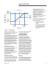
at 95°F is approximatly 1336 MBH
total cooling and 969 MBH sensible
cooling capacity.
Step 6 - Determine Leaving Air
Temperature
Unit sensible heat capacity corrected
for supply air fan motor heat = 969
MBH Sensible - 109.0 MBH Motor
Heat = 860 MBH.
Supply air dry bulb temperature
difference =
Sensible MBH X 1000/1.085 x Supply
CFM
Sensible Btu = 860 MBH x 1000 ÷
(1.085 x 36000 CFM) = 22°F
Supply air dry bulb = 79.5 DB - 22 =
57.5°F Leaving the cooling coil
Supply air wet bulb temperature
difference = (need in RTU catalog
too)
Total MBH x 1000 ÷ 4.5 x Supply CFM
=
Unit enthalpy difference = 1336 MBH
x 1000 ÷ (4.5 x 36000 CFM) = 8.25
Btu/lb.
Leaving enthalpy = h (ent WB) - h
(diff). From Table 6, p. 37, p. 40 h (ent
WB) =
30.9 Btu/lb.
Leaving enthalpy = 30.9 Btu/lb. - 8.25
Btu/lb. = 22.65 Btu/lb.
Supply air wet bulb = 54.0 Leaving
the cooling coil.
Leaving air temperature = 57.5 DB/
54.0 WB
Heating Capacity Selection
Step 1 - Determine Air
Temperature Entering Heating
Module
Mixed air temperature = RADB +
% OA (OADB - RADB) = 70 + (0.10)
(0 - 70) = 63°F
Supply air fan motor heat
temperature rise = 109000 Btu ÷
(1.085 x 36000 CFM) = 2.8°F
Air temperature entering heating
module = 63.0 + 2.8 = 65.8°F
Step 2 - Determine Total
Winter Heating Load
Total winter heating load = peak
heating load + ventilation load -
supply fan motor heat = 720 + 288.6 -
109.0 = 899.6 MBH
Electric Heating System
Unit operating on 460/60/3 power
supply.
From Table 29, p. 70, kw may be
selected for a nominal 105 ton air
handler "C" unit operating at 460-volt
power. The 265 kw heat module
(904.4 MBH) will satisfy the winter
heating load of 899.6 MBH.
Table 28, p. 70 shows an air
temperature rise of 23.2°F for 36000
CFM through the 265 kw heat
module.
Unit supply temperature at design
heating conditions = mixed air
temperature + air temperature rise =
65.8°F + 23.2°F = 89.0°F.
Gas Heating System (Natural
Gas)
From Table 27, p. 70 select the high
heat module (1440 MBH output) to
satisfy winter heating load of 899.6
MBH at unit CFM.
Table 27, p. 70 also shows an air
temperature rise of 37.0°F for 36000
CFM through the heating module.
Unit supply temperature at design
heating conditions = mixed air
temperature + air temperature rise =
65.8°F + 37.0°F = 102.8°F.
Hot Water Heating System
Using a hot water supply
temperature of 190°F and an entering
coil temperature of 65.8°F.
Subtract the mixed air temperature
from the hot water temperature to
determine the ITD (initial
temperature difference).
ITD = 190°F - 65.8°F = 124.2°F.
Divide the winter heating load by ITD
= 1008.6 MBH ÷ 124.2°F = 8.12 Q/
ITD.
From Table 30, p. 71, select the low
heat module. By interpolation, a Q/
ITD of 8.12 can be obtained at a gpm
of 41. Water pressure drop at 41 gpm
is 0.34 ft. of water.
Heat module temperature rise is
determined by:
Total Btu = 1.085 x CFM x Air
temperature rise, °F 1008600 / 1.085 /
36000 = 25.8°F
Unit supply air temperature = mixed
air temperature + air temperature
rise = 65. 8 + 25.8 = 91.6°F.
Steam Heating System
Using a 15 psig steam supply. From
Table 31, p. 71, the saturated
temperature steam is 250°F. Subtract
mixed air temperature from the
steam temperature to determine ITD.
ITD = 250°F - 65.8°F = 184.2°F.
Divide winter heating load by ITD =
1008.6 MBH ÷ 184.2°F = 5.48 Q/ITD.
Table 31, p. 71, select the low heat
module. The low heat module at
36000 cfm has a Q/ITD = 7.44
Heat module capacity, Q = ITD x Q/
ITD = 185°F x 7.44Q/ITD = 1376 MBH
Heat module air temperature rise is
determined by:
Total Btu = 1.085 x CFM x Air
temperature rise, °F 1376000 / 1.085 /
36000 = 35.2°F
Unit supply temperature at design
conditions = mixed air temperature +
air temperature rise = 65.8°F + 35.2°F
= 100.1°F.
Air Delivery Procedure
Supply fan performance tables
include internal resistance of air
handler.
For total static pressure
determination, system external static
must be added to appropriate
component static pressure drop
cooling coil, filters, optional
economizer, optional exhaust fan,
optional heating system, optional
cooling only extended casing).
Supply Fan Motor Sizing
The supply fan motor selected in the
cooling capacity determination was
40.4 BHP and 1097 RPM. Thus, a 40
HP supply fan motor is selected.
Enter Table 39, p. 77 to select the
proper drive. For anair handler "C"
with 40 HP motor, a drive letter A -
1100 RPM is selected.